9000-0447 Rev. I
Page 11 of 42
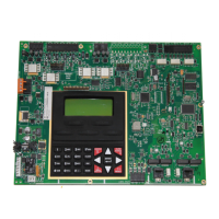
3.0 Basic System Module (BSM)
Table 3-1 Field Wiring Connections
Designation Description Comments
TB1-1 NAC Circuit 1 (+) Class B, Style Y
TB1-2 NAC Circuit 1 (-) Class B, Style Y
TB1-3 NAC Circuit 1 (+) Class B, Style Y
TB1-4 NAC Circuit 2 (-) Class B, Style Y
TB2-1 TRBL Trouble contacts, N/O, 2 amp @ 30 VDC (resistive)
TB2-2 TRBL Trouble contacts, Common
TB2-3 TRBL Trouble contacts, N/C
TB2-4 ALM Alarm contacts, N/O, 2 amp. @ 30 VDC (resistive)
TB2-5 ALM Alarm contacts, Common
TB2-6 ALM Alarm contacts, N/C
TB2-7 Transfer control
TB2-8 Not used
TB3-1 Signaling Line Circuit 1 (+) Class B, Style 4
TB3-2 Signaling Line Circuit 1 (-) Class B, Style 4
TB3-3 Signaling Line Circuit 2 (+) Class B, Style 4 (7100-2, -2D only)
TB3-4 Signaling Line Circuit 2 (-) Class B, Style 4 (7100-2, -2D only)
TB4-1 Resettable Power, 24 VDC 1.0 amp.
TB4-2 Non-resettable Power, 24 VDC 1.0 amp.
TB4-3 System Common
TB4-4 Earth Ground
TB5-1 COM B To LCD-7100 TB1-2
TB5-2 COM A To LCD-7100 TB1-1
TB5-3, -4 Not used
TB6-1 AC “Hot” 120 VAC “Hot”, 50/60 Hz 2 amp., 240 VAC “Hot”, 50/60 Hz 1 amp.
TB6-2 Ground Ground
TB6-3 AC Neutral 120 VAC Neutral, 240 VAC “Hot”
TB7-1 Batt+ Battery terminal (+)
TB7-2 Batt- Battery terminal (-)
TB9-1 DACT Line 1 Tip In (non-power-limited) From street
TB9-2 DACT Line 1 Ring In (non-power-limited) From street
TB9-3 DACT Line 1 Tip Out (non-power-limited) To phone
TB9-4 DACT Line 1 Ring Out (non-power-limited) To phone
TB9-5 DACT Line 2 Tip In (non-power-limited) From street
TB9-6 DACT Line 2 Ring In (non-power-limited) From street
TB9-7 DACT Line 2 Ring Out (non-power-limited) To phone
TB9-8 DACT Line 2 Ring Out (non-power-limited) To phone
 Loading...
