9000-0447 Rev. I
Page 14 of 42
Table 3-3 Battery Standby Chart
Qty
Module
Description
Supv.
Current
Alarm
Current
Total
Supv.
Current
Total
Alarm
Current
BSM-1 Basic System Module, 1 SLC 0.056 A 0.076 A
BSM-2 Basic System Module, 2 SLC 0.065 A 0.085 A
BSM-1D Basic System Module, 1 SLC w/DACT 0.075 A 0.095 A
BSM-2D Basic System Module, 2 SLC w/DACT 0.085 A 0.095 A
PTRM Printer Transient Module 0.020 A 0.020 A
CAOM Class A Option Module 0.001 A 0.001 A
MCOM Municipal Circuit Option Module 0.001 A 0.001 A
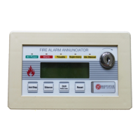
LCD-7100 Optional Remote Serial Annunciator 0.050 A 0.075 A
LDM-7100 LED Driver Module 0.035 A 0.200 A*
INI-7100 Intelligent Network Interface Module 0.040 A 0.040 A
Addressable Modules
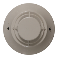
Smoke and heat sensors
Notification Appliances
Aux. Power Devices
Misc. Devices
TOTALS
A Total Supv. Current
B Enter number of standby hours required**
C Multiply Line A times hours in Line B – enter
D Total alarm current from above
E Enter alarm sounding period in hours. (5 minutes = .084 hr.)
F Multiply Line D times Line # - enter
G Total of Lines C & F – enter
H Multiply Line G by 1.2 – enter (Total ampere/hours required***)
NOTE:
* With all LEDs and optional buzzer energized.
** 24 hrs for NFPA 72 protected premises or Central Station signaling, or Auxiliary, or Remote Supervising
Station Fire Alarm Systems.
*** Use the next size battery with a capacity greater than required. Maximum 31 A/H capacity.
 Loading...
