9000-0447 Rev. I
Page 12 of 42
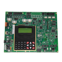
Table 3-2 LEDs Jumpers
Designation Description Comments
LEDs
LED25
Yellow
Line 1 Trouble
LED26 Yellow Line 2 Trouble
Jumpers
W1
Not used
W2 OUT to disable battery
W3 IN – No Local Phone Line 1
W4 IN – No Local Phone Line 2
J6 Connection to keypad
JMP1 Cut for 240 VAC input operation
3.1 Power
3.1.1 AC Input
Connection of the 120/240 VAC, 50/60 Hz power source must be made per the
requirements of the National Electrical Code, NFPA 70, Article 760, the
applicable NFPA requirements, and/or the Authority Having Jurisdiction.
Guidelines to follow are:
• Connections must be to a dedicated branch circuit.
• Connections must be mechanically protected.
• All means of disconnecting the circuit must be clearly marked: “FIRE ALARM
CIRCUIT CONTROL".
• Accessible only to authorized personnel.
• For 240 VAC operation, no conductor shall have a potential greater than 150 V
to ground.
See Table 3-1 for AC input and battery connections.
3.1.2 Battery Connections
• TB7-1 is positive. See Table 3-1.
• TB7-2 is negative. See Table 3-1.
• Observe polarity
See Table 3-3 for Battery Calculations
3.1.3 Auxiliary Power Output, Resettable/Non-resettable (Special Application)
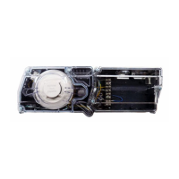
• TB4-1 Resettable, 24 VDC, max. 1.0 amp., FWR. Suitable for use with
projected beam smoke detectors SPB-24, or DH Series duct detectors.
• TB4-2 Non-resettable, 24 VDC, max. 1.0 amp., FWR. Suitable for use with the
Firemark door holders.
NOTE: Total output is 1.0 amp max. combined.
• TB4-3 Common negative
• TB4-4 Not used
3.1.4 Earth Ground Connection
• TB4-4 Earth Ground
IMPORTANT: Alwa
s a
l
AC
ower first
then connect the batteries.
 Loading...
