9000-0447 Rev. I
Page 15 of 42
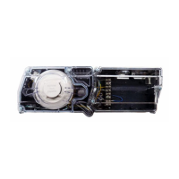
3.3 Notification Appliance Circuits
The 7100 provides two (2), 24 VDC Class B, Style Y
notification appliance circuits. Class A, Style Z operation is
accomplished by adding the Class A Option (CAOM) Module.
Wiring Instructions
• NAC 1 - TB1-1 (+), TB1-2 ( - )
• NAC 2 - TB1-3 (+), TB1-4 ( - )
(Polarity markings indicate the polarity of the circuit in
alarm condition).
Use U.L. Listed End of Line Resistor EOL-N (47K),
P/N 4700-0512
Circuit Ratings
• 24 VDC regulated
• Max. alarm load 1.5 amp./circuit
• Ground fault test impedance: 20 kOhms
• 18 AWG minimum
• If synchronization of strobes is required
MDL-FC Synchronization Modules must be connected.
Class B, Style Y operation only
Special application: See Compatibility Addendum/
P/N 9000-0427 for a list of Gamewell-FCI Approved, UL Listed notification appliances.
• Supervised
• Power-limited
NOTE: The CAOM module is furnished with the End of Line resistor installed.
3.4 Signaling Line Circuits
The 7100 provides one (1), or two (2), 24 VDC Class B,
Style 4 signaling line circuits. Class A, Style 6 or 7
operation is accomplished by adding the Class A Option
(CAOM) Module. See Figure 7 for Style 4 or 6 wiring, and
Figure 8 for Style 7 wiring.
Wiring Instructions
SLC 1 - TB3-1 (+), TB3-2 ( - )
SLC 2 - TB3-3 (+), TB3-4 ( - ) (7100-2 only)
(Polarity markings indicate the polarity that should
be maintained throughout the circuit. Polarity must be
observed on all devices connected to the circuit).
Circuit Ratings
24 VDC (nominal)
Current: 0.090 amp max. (supervisory)
0.097 amp max. (alarm)
0.750 amp max. (short circuit)
• 40 Ohms max. line resistance
• 0.5 µf max. line capacitance
• Ground fault test impedance: 20 kOhms
• 18 AWG minimum, straight lay or twisted-pair
unshielded
• Power-Limited
• Supervised
See Compatibility Addendum/ P/N 9000-0427 for a list of Gamewell-FCI Approved, UL
Listed sensors and modules.
Figure 6 Notification
Appliance
Circuit Wiring
NOTE: A white wire lead of The NCM-1
module (if used) must be connected to earth
ground.
Figure 7 Signaling Line Circuit Wiring
 Loading...