10 LCD-SLP Product Installation Document — P/N LS10045-000GF-E:E 12/16/2019
Section 3: Wiring
3.1 LCD-SLP Wiring Requirements
Table 3.1.1 lists the LCD-SLP wiring requirements.
3.2 LCD-SLP Wiring Connections
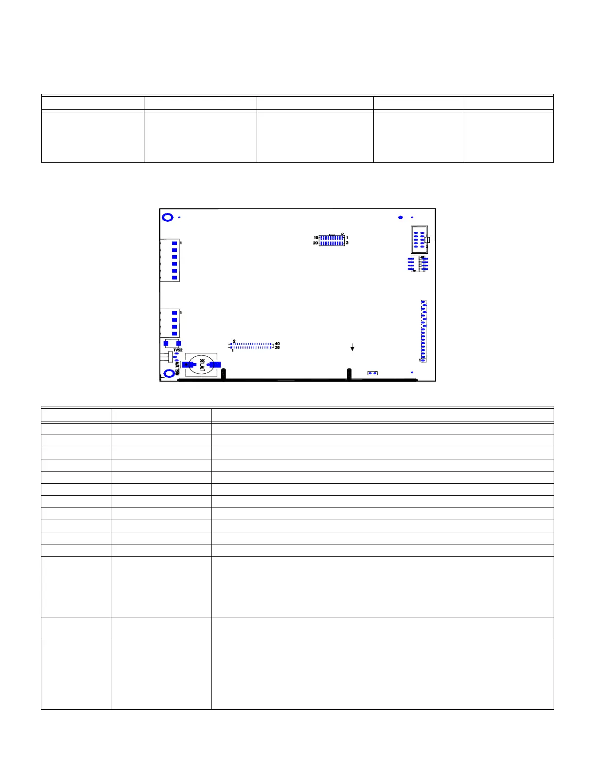
Figure 3.2.1 illustrates the LCD-SLP circuit board diagram.
Figure 3.2.1 LCD-SLP Circuit Board Diagram
Table 3.2.1 lists the LCD-SLP installation wiring terminals.
Circuit Type
Circuit Function Wire Requirements D i s t a n c e Typical Wire Type
RS-485
(Class 2 Power-
Limited)
Connects to the LCD-E3,
LCD-SLP, ASM-16 and
ANU-48 modules.
Twisted-unshielded pair
with a characteristic
impedance of 120 Ohms.
18 AWG
(0.78 mm2) minimum.
3,000 ft.
(.914 m) (maximum)
16 AWG (1.30 mm2)
Table 3.1.1 LCD-SLP Wiring Requirements
Designation Description Comments
TB1-1 RS-485 COMM A Communications IN (See Notes 1 and 2)
TB1-2 RS-485 COMM B Communications IN (See Notes 1 and 2)
TB1-3 RS-485 COMM A Communications OUT (See Note 3)
TB1-4 RS-485 COMM B Communications OUT (See Note 3)
TB2-1 +24 V +24 V non-resettable power IN (See Notes 1 and 2)
TB2-2 GND IN GROUND IN (See Notes 1 and 2)
TB2-3 +24 V OUT +24 V non-resettable power OUT (See Note 2)
TB2-4 GND OUT GROUND OUT (See Note 2)
TB2-5 GND Extra Ground
TB2-6 Earth Ground Earth Ground
J5 Local Connection RS-485 communications and power (ribbon cable local only) (See Note 3)
J6 Keypad Lock Jumper or Keyswitch:
1. To use the Jumper, do either of the following:
JMP IN = Disabled
JMP OUT = Enabled OR
2. To use the keyswitch, connect the PK-625 keyswitch. This keyswitch is keyed
alike with the door lock, and must be operated to activate the keypad.
W1 RS-485 Termination W1 should be ON (top 2 pins), if it is the first or last device on the RS-485 bus.
Otherwise, W1 should be OFF (bottom 2 pins).
SW1 Display Address Binary Switch Addressing
Table 3.2.1 LCD-SLP Installation Wiring Designations
LCD-SLP
TB2
DISPLAY
TB1
RS485
J6
KEYSWITCH
J1
J5
LOCAL
HOST
SW1
1
4
OVERLAYS LEDS
J4
JTAG
J3 DISPLAY
10 9
12
W1
ON
OFF
NOTE 1:
CONNECT
KEYSWITCH
CABLE TO J6.
 Loading...