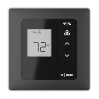
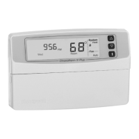
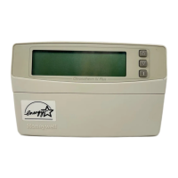
INNCOM E7 THERMOSTAT USER GUIDE
36-00013—02 8
e7 24 VAC POWER AND HVAC SIGNAL (INNCOM PIN 62-1464 R) - H1
e7 100-277VAC POWER AND HVAC SIGNAL HARNESS (INNCOM P/N 62-1455) - H1
Part Number Color Typical Function
1 Green Ground
2 Red 24 Vac
3 Black Common
4 Blue High Fan
5 Brown Medium Fan or Second Stage Heat
6 Yellow Cold Water Valve (FCU) or Compressor Signal (Heat Pump)
7 White Hot Water Valve (FCU) or Reversing Valve (Heat Pump)
8 Grey Valve Power
9 Violet Fan Power
10 Orange Low Fan
Part Number Color Typical Function
1 Green Ground
2 Black Line
3 White Neutral
4 Yellow High Fan
5 Orange Medium Fan or Second Stage Heat
6 Red Cold Water Valve (FCU) or Compressor Signal (Heat Pump)
7 Brown Hot Water Valve (FCU) or Reversing Valve (Heat Pump)
8 Grey Valve Power
9 Violet Fan Power
10 Blue Low Fan

 Loading...
