NFS2-3030 Listing Document — P/N LS10006-051NF-E:F2 5/19/2022 25
• Wind
• Elevator piston effect
• the HVAC system
– Principles of Smoke Control: The smoke control system uses a building’s ventilation system to exhaust the fire floor and pressurize
surrounding floors. The three major considerations for smoke control are:
• Smoke containment
• Purging
• Door-opening forces
– HVAC Equipment: For smoke control applications, HVAC systems must have the following capabilities:
• Supply outside air to a space
• Return air from a space
• Exhaust air from a space to the outside
– SCS/SCE: The SCS-8 Smoke Control Station and the SCE-8 Smoke Control Expander can be used in conjunction with this panel to provide
smoke control capabilities. The SCS-8L Smoke Control Lamp Driver and the optional SCE-8L are used with the smoke control system to
provide graphic annunciation.
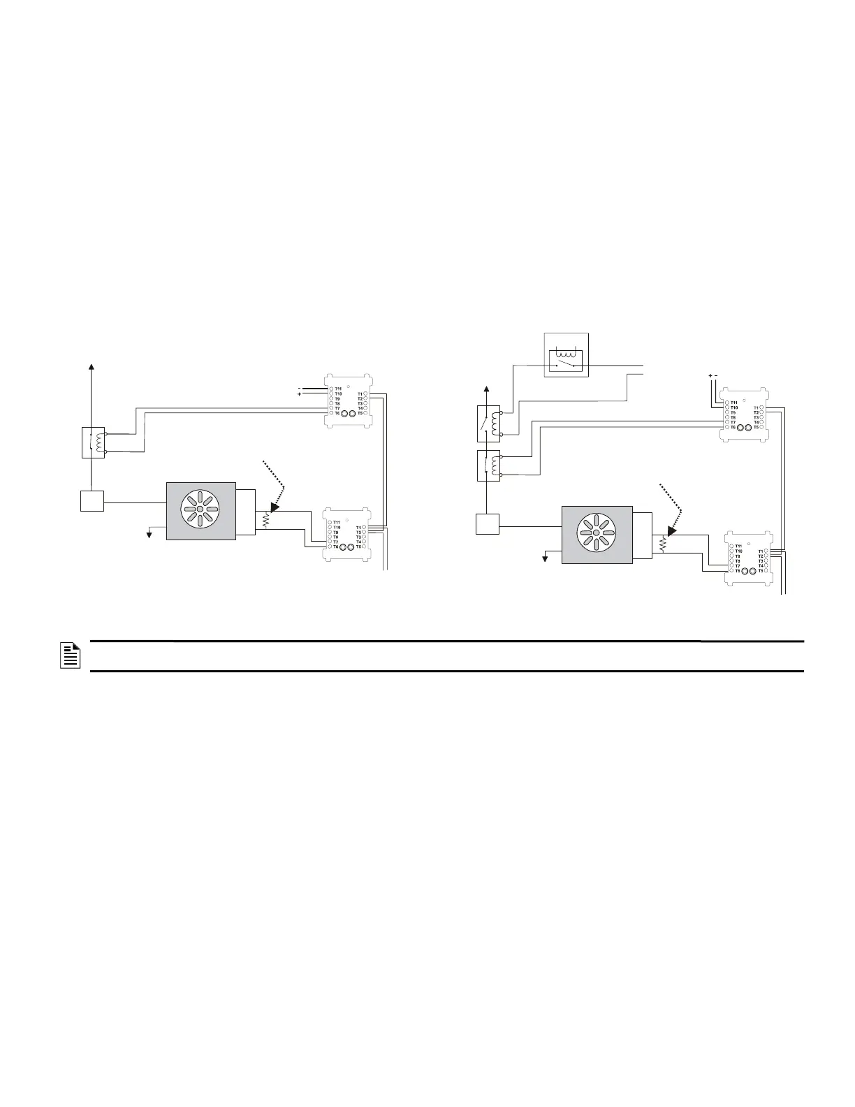
– Dedicated/Non-dedicated Smoke Control System Wiring Diagrams: Figures 2 and 3 below show wiring for a dedicated and non-dedicated
smoke control system performing the same fan control functions. The system in Figure 3 features an Energy Management System. Refer to the
SCS Series Manual, document number 15712, for more detailed information on the Smoke Control System.
3 Functionality
The following are approved functions for the NFS2-3030.
• Drift Compensation
• Remote Programming
• Extent/Limitations of Synchronization
– No synchronization across networks
• Multiple Detector Operation
– Units employing multiple detector operation shall include a minimum of two detectors in each protected space and reduce the detector
installation spacing to 0.7 times the linear spacing in accordance with National Fire Alarm Code, NFPA.
• Positive Alarm Sequence
• Pre-signal
• Alarm verification
• Two-wire compatibility
– One alarm per initiating device circuit
• Polling Style limitations
– Polling Style is FlashScan or CLIP (Classic Loop Protocol)
1. All detectors and modules on an SLC may be programmed as FlashScan. All detectors and modules must be FlashScan type devices.
Maximum number of devices per SLC: 159 detectors, 159 modules.
2. All detectors and modules on an SLC may be programmed as CLIP. Detectors and modules may be a mix of CLIP and FlashScan type
devices, but all must be programmed as CLIP. Maximum number of devices per SLC: 99 detectors, 99 modules.
3. All detectors may be programmed as CLIP, all modules as FlashScan, on an SLC. Detectors may be a mix of CLIP and FlashScan type
devices, modules must all be FlashScan type devices. Maximum number of devices per SLC: 99 CLIP detectors, 159 FlashScan modules.
NOTE: When operating as a Protected Premises Control Unit, the ONYXWORKS-WS is UL Listed for monitoring and control of fire, smoke
control, and mass notification devices.
Figure 2 Dedicated Smoke Control System
SLC
Service
Disconnect
Switch
1a listed
contactor
Power
Source
Power
Return
FAN
Listed 24VDC
Power Source
SLC Control
Module
SLC Control
Module
Listed Sail
Switch
ELR-47K
(use 3.9K listed ELR with FZM-1)
N/O
COM
N/C
Figure 3 Non-Dedicated Smoke Control System
Listed
Contactor for
Energy
Management
System
1b listed
contactor
Service
Disconnect
Switch
Energy
Management
System
SLC
Power
Return
FAN
Listed Sail
Switch
SLC Control
Module
SLC Monitor
Module
ELR-47K
(use 3.9K listed ELR with FZM-1)
N/O
CO
N/C
Listed
24VDC
Power
Source
Listed
24VDC
Power
Source

 Loading...


