NFS2-3030 Listing Document — P/N LS10006-051NF-E:F2 5/19/2022 9
1.2.6 Loop Control and Loop Expander Modules (LCM-320/LEM-320)
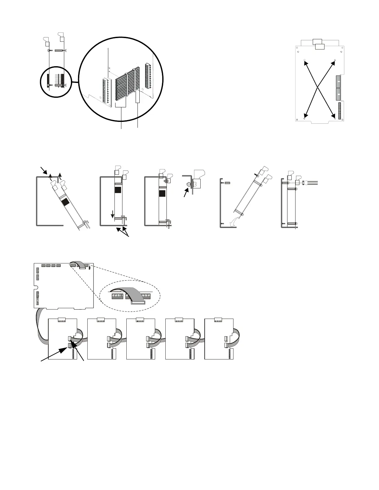
Note the following when installing the LCM-320/LEM-320 boards:
• LCM-320 and LCM-320/LEM-320 combinations can be mounted adjacent to the fire panel CPU or below in a secondary chassis within the same
enclosure.
• Mounting two pairs of loop control and expander modules in one chassis position may cause intermittent electrical interference. If this occurs,
move one pair to a separate chassis position.
• Set switches and other board settings before layering other boards on top.
• Each LCM-320 should be assigned a unique SLC loop number but does not have to match the module’s location in the daisy chain.
• Up to five loop control modules and loop expander modules can be installed on the fire panel.
• If the loop is programmed for CLIP mode, do not program more than 99 devices on the loop. Refer Loop Configuration on page 42.
• Set SW1 on each LCM-320 to a unique SLC loop number using addresses 1, 3, 5, 7, or 9. If an LEM-320 is coupled with the LCM-320, it will
have the next higher even number.
CAUTION: If the stacker-connector is
installed upside-down, the short-pin
end of the plug can fail to make a
secure connection when plugged
through the Loop Control Module.
Top Slot
Bottom Slots
J3 on the LCM-320
“Data out”
NOTE: The red stripe on the ribbon cable
indicates position 1. Position 1 of the ribbon
cable should line up with position 1 on J7 of
the CPU and J1 and J3 of the LCM-320.
Loop Expander Module mounted
behind Loop Control Module
Red stripe on the ribbon cable
is indicated by the dark line.
Module
Screw
Standoff
locations
The long-pin end plugs
directly into the back of the
Loop Control Module board
The short-pin end plugs
directly into the top of the
Loop Expander Module plug
Connecting Loop Control Modules to Loop Expander Modules
Inserting a Two-Layer Module into CHS-4N or CHS-M3 Inserting a Pair of Loop Control and Expander
Modules into a CHS-4L
Angle tab on
loop control
module into slot
on the CHS-4L
Use a slimline
screwdriver (3/32”)
to fasten down the
LEM-320 through
the hole in the
LCM-320 board
J2 on the LCM-320
“Data in”
WARNING: Install the ribbon cable as
shown. Do not force or modify the cable
to fit any other way. Equipment damage
can result from incorrect alignment.
Connecting Multiple Pairs of Loop Control and Expander Modules
WARNING: Use specified stand-off
mounting locations only. Do not use
corner holes for installation purposes.
It is critical that all mounting holes of
the fire alarm control panel are
secured with a screw or standoff to
ensure continuity to ground.
Figure 8 Connecting the Loop Control and Expander Modules

 Loading...


