12 NFS2-640 Operations P/N 52743:L4 06/10/19
Section 2: Use of the Controls
2.1 Introduction
Listing of the controls and indicators and where to find information on their use:
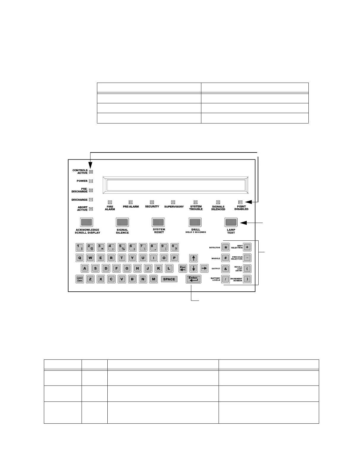
Figure 2.1 NFS2-640 Control Panel Keys and Indicators
2.2 System Status Indicator LEDs
The control panel contains 12 labeled LEDs described in Table 2.1.
Operating Components Covered in
Twelve System Status Indicator LEDs “System Status Indicator LEDs” on page 12
Five Control Keys “Control Keys” on page 13
Programming Keypad “Programming Keypad” on page 15
Control Keys
(Refer to
page 13).
Status Indicator
LEDs (Refer to
Section 2.2 below)
Programming Keypad
(Refer to page 15
Function keys
(Refer to page 15
Cursor movement (arrow) keys,
ESC key, and ENTER key. (Refer to page 15
NFS2_640-keypad.wmf
80-character (2 x 40) Liquid Crystal
Display.(LCD)
Indicator Color When Active To Turn Off
CONTROLS
ACTIVE
Green LIghts when the panel assumes control of local
operation as primary display.
Turns off automatically when another panel
assumes control of local operation.
POWER Green Lights when the proper primary AC power is
applied. Remains lit while power is applied.
Always lit with AC power applied.
PRE-DISCHARGE Red Lights when any of the releasing zones have been
activated, but have not yet discharged a releasing
agent.
Turns off automatically when no releasing
zones are in the pre-discharge state.
Table 2.1 Descriptions of System Status Indicator LEDs (1 of 2)

 Loading...


