44 NFS2-640 Operations P/N 52743:L4 06/10/19
Read Status Operation Viewing and Printing a Read Status
• Device Status The status of the detector: Normal, Alarm, or Test.
• Type Code The software Type Code that identifies the type of detector. (Refer to “Point
Programming” in the NFS2-640 Programming Manual.)
• Default CBE Zone Selection This is the first zone in the 5 zone CBE list. Defaults are Zone
001 (Heat detectors) Zone 002 (Ion detectors) Zone 003 (Photo detectors) Zone 004 (Laser
detectors) Zone 005 (Multisensor). Values may differ depending on point programming.
• Current alarm reading (xxx%) The current alarm reading of the detector, as a percentage of
the alarm sensitivity setting.
• Alarm sensitivity level (Ax) The alarm sensitivity (x=1-9) entered in the Detector Sensitivity
Screen.
• Pre-Alarm sensitivity level The Pre-Alarm Sensitivity (1-9; 0 = Pre-Alarm not used) entered
in the Detector Settings Screen.
• Cooperative Multi-Detector selection A smoke detector programmed to evaluate readings
from nearby detectors in making Alarm or Pre-Alarm decisions. Cooperative Multi-Detector
sensing also allows the combination of ionization with photoelectric technology in reaching an
alarm decision.
* – Multi-not used.
A – combines the detector’s alarm decision with the next SLC address above.
B – combines the detector’s alarm decision with the next SLC address below.
C – combines the detector’s alarm decision with the next SLC address above and the next SLC
address below.
• Alarm Verification (* or V)
* – Alarm Verification not programmed for this detector.
V – Alarm Verification enabled.
Alarm Verification is a user-defined global time function that can reduce the number of
nuisance alarms. Refer to page page 39 for more information.
• Device SLC Address The SLC address of the detector.
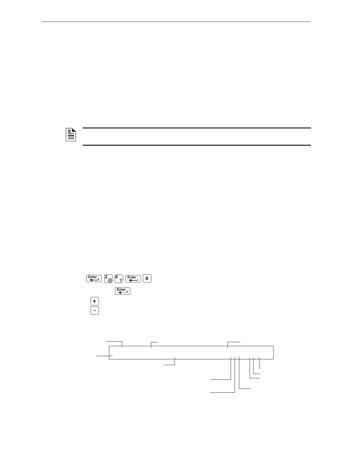
How to View Read Status for a Control/Relay or Monitor Module
From the “Read Status” screen, press 0, then press the ENTER
key. You can now view Read Status for a monitor or a con-
trol/relay module as follows: press
MODULE, enter the SLC
address, then press the
ENTER key. For example, to read the sta-
tus of a FCM-1 module 2M147: press
MODULE, enter 2 then
147, then press the
ENTER key. The control panel now displays
information about the module as shown in Figure 4.2.
The display and descriptions of the fields are shown below:
Figure 4.2 Sample Control/Relay or Monitor Module Read Status Display
NOTE: Refer to “Detector Sensitivity Settings” in the NFS2-640 Programming Manual for more
information on the Pre-Alarm and Alarm Sensitivity settings
SLC address
next device
previous device
Type Code (CONTROL)
Walk Test selection:
W selected for Walk Test
* not selected
Label for the module
Extended 12-
character
custom label
SLC Address (001-159)
M (module)
SLC number (1 or 2)
Switch Inhibit: I selected, * not selected
Device status
OFF CONTROL INTENSIVE CARE UNIT
DOORHOLDER#2 Z000 *O* 2M147
Default CBE zone selection
Silenceable: O = selected, * = not selected (default)

 Loading...


