N200-102-00 3 I56-3947-202
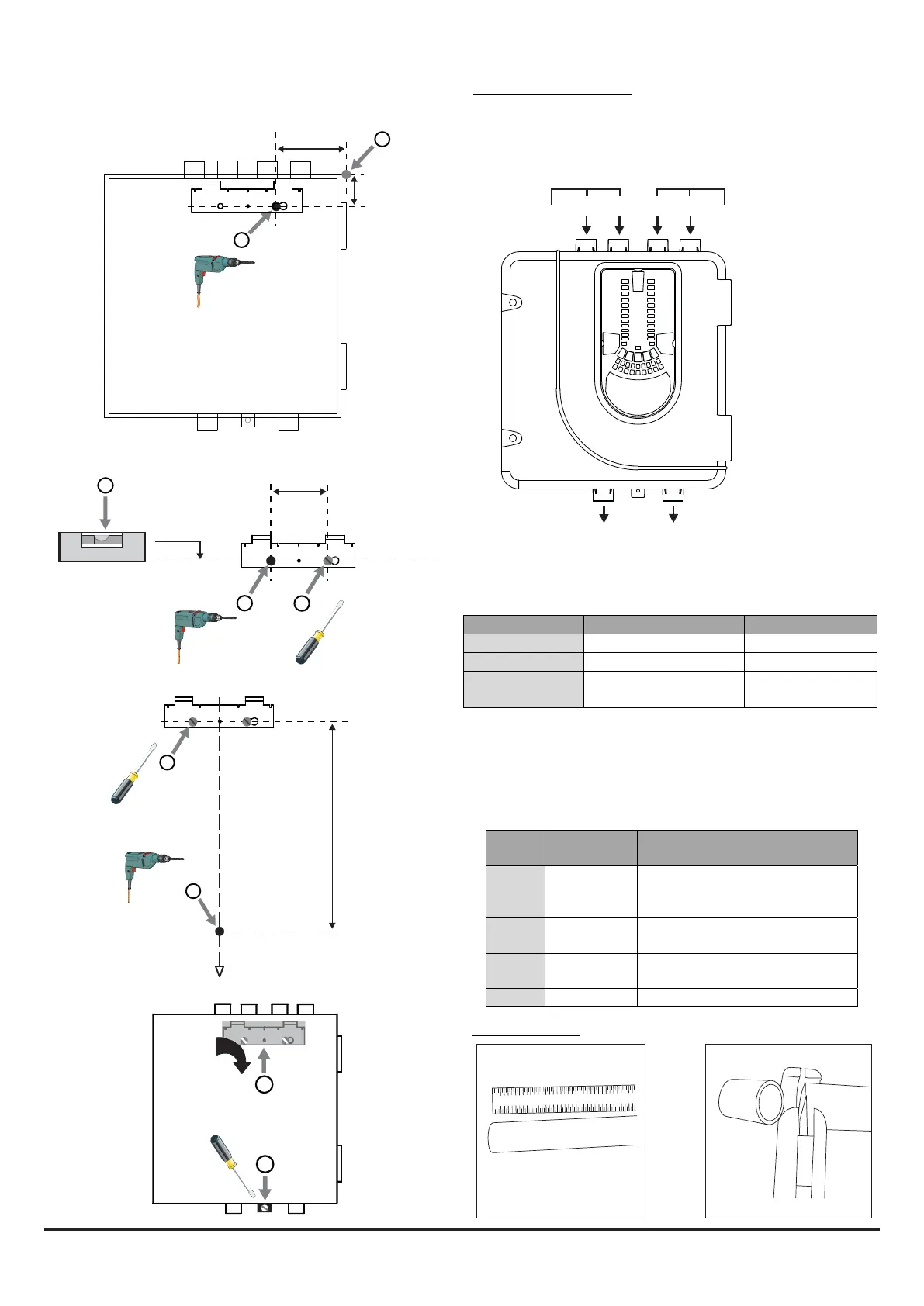
Figure 7: Sequence (1 to 9) to Mount the Detector on the Bracket
Pipe Installation
1 2 3 4 5 6 7 8 9 10 1112 13 14 15 16
17 18
1 2 3 4 5 6 7 8 9 10 1112 13 14 15 16 17 18
99 mm
41
1
2
mm
90 mm
4
3
0.00
o
5
329 mm
6
7
7a
7b
7c
7d
8
9
1 2
FAASTLTMODEL INLETPIPEHOLE OUTLETPIPEHOLE
NFXI‐ASD11 1and/or2 5
NFXI‐ASD12 1and/or2 6
NFXI‐ASD22 Channel1‐1and/or2
Channel2–3and/or4
5
6
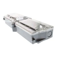
Pipe Hole Conguration
Figure 8 below shows the pipe holes available on the unit. Each
unit has 2 pipe holes per channel connected together like a T-Piece.
If using a 1 channel unit, holes 3 and 4 do not function. Use Table
1 to locate the holes required for the installation:
Figure 8: Pipe Holes
Table 1: Pipe Holes Used for Each FAAST LT Model
Note 1: Pipe holes not used should be kept sealed.
Note 2: Do NOT glue pipes into the pipe holes.
Table 1a: Maximum Number of Pipe Holes Allowed Per Channel
for EN54-20 Compliance
All gures quoted using highest (level 1) sensitivity.
1
2
3
4
5
6
CHANNEL 1 CHANNEL 2 (ONLY FUNCTION
ON 2 CHANNEL UNITS)
CHANNEL 1 (NOT
USED FOR COMMON
CHAMBER UNIT)
CHANNEL 2 (ONLY FUNCTIONS
ON 2 CHANNEL AND COMMON
CHAMBER UNITS)
CLASS PIPELENGTH
(m)
MAXNUMBEROFHOLESPER
CHANNEL
C 100 18(5x2mm,6x2.5mm,3x3mm,
3x3.5mmand1x4mm)+4mm
nonsensingendhole
C 160(2x80)
UsingT‐Piece
9holesperbranch(3x2.5mm,6x
3mm)+3mmnonsensingendhole
B 100 6(2x3.5mm,2x4mm,2x5mm
incendhole)
A 80 3(1x5mm,2x6mmincendhole)

 Loading...