N200-102-00 6 I56-3947-202
Figure 10: Address Switches
Each aspiration channel uses loop communications to report its
status information to the CIE (Fire Panel). As a factory default,
the unit will report smoke alarm and sensor information at an
associated sensor address and general alerts and faults on a
different module address.
Sensor
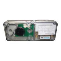
The sensor address is set on rotary decade switches on the back
of the smoke sensing devices. The smoke sensors are located
under the sensor cover inside the unit (see Figure 9). The Smoke
Sensors section of Service - later in the manual - shows how
to remove the sensors. As supplied, the default for channel 1 is
Address 1; in 2 channel units (or when two sensors are tted) the
second device is set to Address 2.
Any sensor address may be used except 0, whilst respecting the
panel’s rules on co-operative Multi-Sensing* (see below) between
the VIEW™ smoke sensors.
Note: The sensors communicate with the re panel through the
loop connection whether the 24VDC power supply is on or not.
Module
The module address is set by means of rotary decade address
switches located behind the door of the unit. Use a screwdriver to
rotate the wheels to the desired address. The selected address
refers to channel 1; on 2 channel units the device assigns the next
(+1) module address to channel 2 automatically. Hence, address
159 is not valid for channel 1. (Note: for control panels that use
only 99 addresses, 99 is invalid for channel 1.)
Note: The module address will only respond to a panel poll when
in Normal mode with the 24VDC power supply on.
* Co-Operative Multi-Sensing
Depending upon the panel used, the rules to dene the co-operative
Multi-Sensing between the VIEW™ smoke sensors differs. This
mode will allow an even higher sensitivity, but is only to be used for
the sensors within a single NFXI-ASD12.
How to Set this up for the NF300, NF3000, NF500, NF5000 and
ID3000 Panels
The co-operative Multi-Sensing is automatically activated if the
VIEW™ sensors on a loop are set to adjacent sensor addresses
and if they are also put into the same zone. Additionally, if cells
are being used, the cell numbers for the co-operative sensors must
also be the same.
How to Set this up for the NF50-A, NF50, NF50-S, ID60 and
Pearl Panels
The co-operative Multi-Sensing is automatically activated if the
VIEW™ sensors on a loop are put into the same AWACS group.
Setting an AWACS group to 0 will disable co-operative Multi-
Sensing for that sensor.
SETTING THE ADDRESSES POWERING UP
Using Default Settings
1. Connect a suitable 24VDC supply (complying with European
Standard EN 54-4) to pins 1 and 2 on terminal block T1 (See
Table 2)
2. Check the voltage at the connector. Make sure it is within the
required voltage range.
3. If the voltage is within the specied range, connect the power
connector to the unit.
4. Close and secure the housing door; verify the fan starts up and
air ows out of the exhaust port. The unit takes 1-3 minutes to
initialise and stabilise in normal mode.
EXTERNAL RESET
The default setting for the congurable external input is Device
Reset (terminal block T8). A short circuit connection between these
terminals will cause the FAAST LT unit to perform a reset.

 Loading...