N200-102-00 5 I56-3947-202
Table 2: Wiring Terminal Designations
(Note - Terminals marked CH2 will only be available on 2 channel
models)
No. Function
1 Ext Power In +
Primary PSU
T1
2 Ext Power In -
Primary PSU
3 Aux Power In +
Not used in default
4 Aux Power In -
Not used in default
5 NC Alarm Relay
CH1
T2
6 C Alarm Relay
CH1
7 NO Alarm Relay
CH1
8 NC Alarm Relay
CH2
T3
9 C Alarm Relay
CH2
10 NO Alarm Relay
CH2
11 NC Fault Relay
CH1
T4
12 C Fault Relay
CH1
13 NO Fault Relay
CH1
14 NC Fault Relay (AUX)
CH2
T5
15 C Fault Relay (AUX)
CH2
16 NO Fault Relay (AUX)
CH2
17 Sounder Output 1 -
47 k-ohm EOL Resistor
T6
18 Sounder Output 1 +
19 Sounder Output 2 -
47 k-ohm EOL Resistor
T7
20 Sounder Output 2 +
21 Configurable Input +
(Reset)
Default is active = short circuit
(unsupervised)
T8
22 Configurable Input -
(Reset)
23 Not Used
T9
24 Loop out -
25 Loop switched out +
To use isolator
26 Loop in -
T10
27 Loop in +
28 Loop not switched out +
Internally connected to 27
RELAY ACTION: NOTES
ALARM 1 or 2 Controlled by panel when it determines
alarm condition has been met.
Set ON and OFF by panel; not latched
FAULT 1 or 2 When FAULT CONDITION on Ch1 or Ch2
or a common FAULT occurs. Fault is also
signalled when in Service Mode and when
the device is unpowered.
Fault state is not latched.
SOUNDER 1 or 2 Set ON when a channel is in ALARM.
Sounder 1 corresponds to Ch1 and
Sounder 2 corresponds to Ch2
Default condition = set on in ALARM.
Table 3: Relays
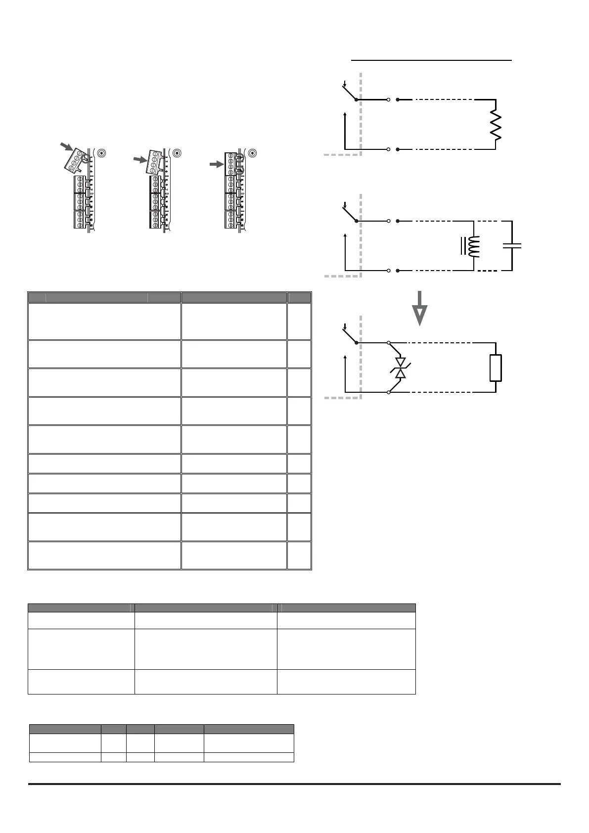
Fitting the Terminal Blocks
To insert the terminal blocks into the unit use the following method:
1 Insert a corner of the block into the slot (see a).
2 Push the length of the block into the slot until the block ‘clicks’
into place, the 2 upper hooks on the block should be visible
(see c).
a
b c
Table 3a: Relay Electrical Specication
SPECIFICATION MIN MAX UNITS COMMENTS
Contact Rating 2
0.5
A
A
30 VDC resistive load
30 VAC resistive load
Life Time 10
5
Operations
1N6284CA
FAAST LT
FAAST LT
CL
FAAST LT
R
L/C
WARNING: Switching Inductive Loads
Inductive loads can cause switching surges, which may
damage the module relay contacts (see above).
To protect the relay contacts, connect a suitable Transient
Voltage Suppressor (for example 1N6284CA ) across the
load as shown.
Alternatively, for unsupervised DC applications, t a diode
with a reverse breakdown voltage greater than 10 times the
circuit voltage.

 Loading...