N200-102-00 4 I56-3947-202
WIRING INSTALLATION
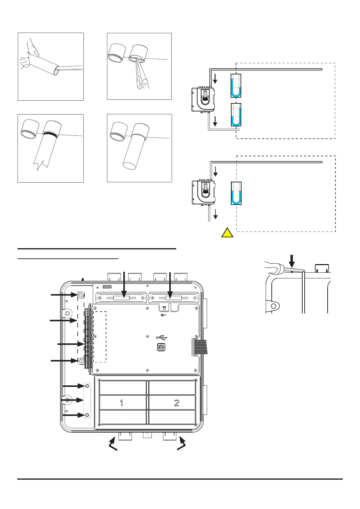
Power, Alarm and Control Connections
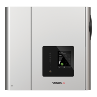
Figure 9: Inside the Detector
CHANNEL 2 FILTER
POWER AND
ALARM
CONNECTIONS
CHANNEL 1 FILTER
USB PORT
SENSOR COVER
POSITION FOR
TEST MAGNET
MODULE MOUNT
Exhaust Pipe
SAMPLING AREA
SAMPLING AREA
1 2 3 4 5 6 7 8 9 10 1112 13 14 15 16 17 18
1 2 3 4 5 6 7 8 9 10 1112 13 14 15 16 17 18
5 6
EARTH BAR
MOUNT
EARTH BAR
MOUNT
F-LT-EB
EARTH BAR
(OPTIONAL)
Note 1: All wiring should comply with local
requirements and regulations.
Note 2: Loop wiring must observe the
recommendations of the panel manufacturer
1 2 3 4 5 6 7 8 9 10 1112 13 14 15 16 17 18
1 2 3 4 5 6 7 8 9 10 1112 13 14 15 16 17 18
3 4
Whenever the FAAST LT is installed outside the risk area, return of
the exhaust air back into the protected area can reduce ow faults
due to pressure difference.
!
PLACE
WIRING
LABEL
HERE
If the FAAST LT door is closed for a long time
(especially at high temperatures) it may be
necessary to use a at-bladed screwdriver
between the two tabs at the top of the unit to
lever open the door (as shown above).
MODULE MOUNT
F-LT-PMB
MODULE MOUNT
KIT (OPTIONAL)*
*If required, an input/output module
can be installed into the FAAST LT
unit. The optional module mount kit
(F-LT-PMB) will be needed for this.

 Loading...