SCS Series Manual — P/N 15712:L 7/18/16 131
Non-dedicated Smoke Control System Wiring Diagrams Ratings and Wiring Diagrams
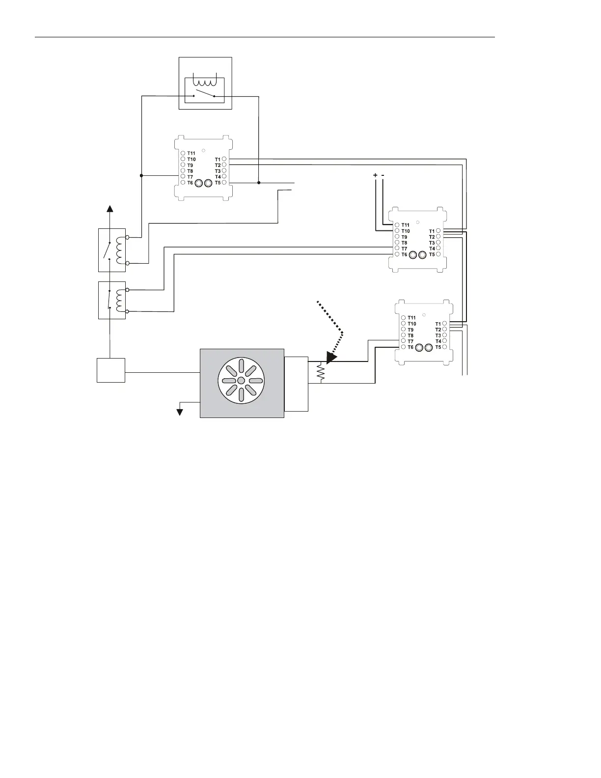
Figure 5.22 Fan Control, Non-dedicated System - FSCS Switch Group Type 8
Figure 5.22 depicts a fan in a non-dedicated system with the capability of
ON and OFF control and verification of the ON state, switch group
type 8. In the above configuration, the CON
ON⁄OP
CM is deactivated and the CON
OFF⁄CL
CM is deactivated. These two control modules are
always in the opposite state when the smoke control system is in operation and are always deactivated during normal operation. The
CON
ON⁄OP
CM is wired in parallel with the EMS; when wired in parallel with the EMS the CM must be a relay module. When the
CON
ON⁄OP
CM and the CON
OFF⁄CL
CM are deactivated, the EMS is free to control the fan. In this case the EMS is OFF, so no power is being
supplied to the fan. When no power is supplied to the fan, the fan is
OFF and the sail switch is CLOSED, indicating no airflow in the duct. The
VER
ON⁄OP
MM monitors the OPEN position of the sail switch, which would indicate when the fan is ON. In this case the VER
ON⁄OP
MM is
deactivated because the fan is
OFF due to the EMS. When the CON
ON⁄OP
CM is activated for smoke control, the CON
ON⁄OP
CM overrides
whatever state the EMS is in and closes the normally open contactor, thus supplying power to the fan and turning it
ON. When the
CON
OFF⁄CL
CM is activated for smoke control, the CON
OFF⁄CL
CM opens the normally closed contactor and turns the fan OFF, overriding
whatever state the EMS is in.
Switch group type 9 is used for
ON and OFF control and verification of the ON and OFF state. Since it is possible to determine both ON and OFF
verification from switch group type 7 or switch group type 8, switch group type 9 would only be necessary for redundancy in verifying the
state of the fan. For example, if switch group type 7 is used instead of switch group type 8, the
OFF state of the fan would be verified when
the monitor module is activated and the
ON state of the fan would be verified when the monitor module is deactivated. Utilizing switch group
types 7 or 8 also saves the use of an additional monitor module. Switch group type 9 would use two monitor modules to provide the same
verification as types 7 or 8.
Power Source
Service
Disconnect
Switch
ELR-47K
(use 3.9K listed ELR with FZM-1)
Listed
Sail
Switch
N/O
COM
N/C
Power Return
VER
OFF/CL
MM
(deactivated)
fan-nf8-fs-2.wmf
SLC Loop
FAN OFF
Energy
Management
System
Listed
24 VDC
Power Source
FMM-1
CON
ON/OP
CM
(deactivated)
FRM-1
1a listed
contactor
1b listed
contactor
Listed
24 VDC
Power Source
FCM-1
CON
OFF/CL
CM
(deactivated)
*If the SLC device
does not match the
one in this figure, refer
to the SLC manual
appendix, which
contains wiring
conversion charts for
type V and type H
modules.

 Loading...


