130 SCS Series Manual — P/N 15712:L 7/18/16
Ratings and Wiring Diagrams Non-dedicated Smoke Control System Wiring Diagrams
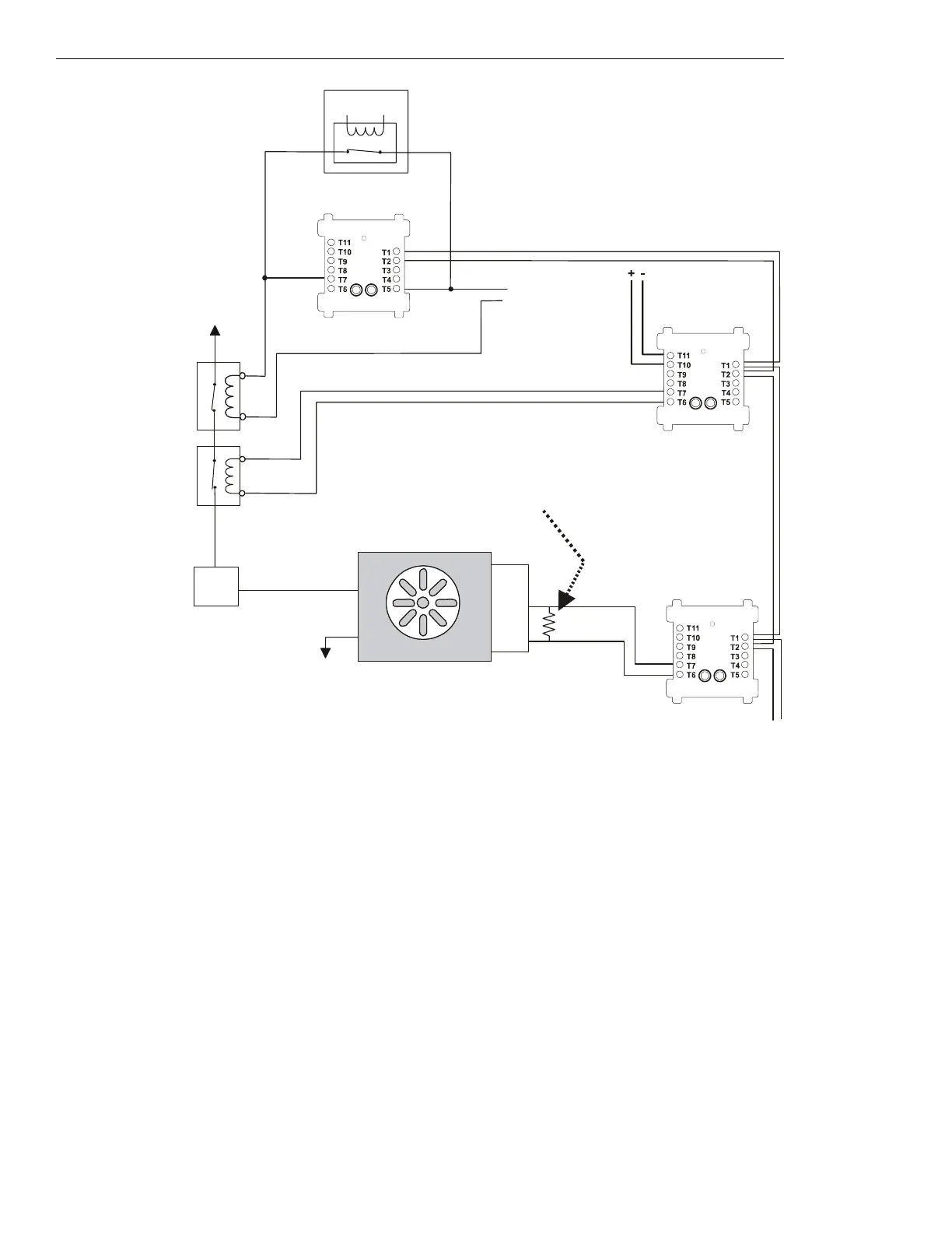
Figure 5.21 Fan Control, Non-dedicated System - FSCS Switch Group Type 7
Figure 5.21 depicts a fan in a non-dedicated system with the capability of
ON and OFF control and verification of the OFF state, switch group
type 7. In the above configuration, the CON
ON⁄OP
CM is deactivated and the CON
OFF⁄CL
CM is deactivated. These two control modules are
always in the opposite state when the smoke control system is in operation and are always deactivated during normal operation. The
CON
ON⁄OP
CM is wired in parallel with the EMS; when wired in parallel with the EMS the CM must be a relay module. When the
CON
ON⁄OP
CM and the CON
OFF⁄CL
CM are deactivated, the EMS is free to control the fan. In this case the EMS is ON, so power is being sup-
plied to the fan. When power is supplied to the fan, the fan is
ON and the sail switch is OPEN, indicating airflow in the duct. The VER-
OFF⁄CL
MM monitors the CLOSED position of the sail switch, which would indicate when the fan is OFF. In this case the VER
OFF⁄CL
MM is
deactivated because the fan is
ON due to the EMS. When the CON
ON⁄OP
CM is activated for smoke control, the CON
ON⁄OP
CM overrides
whatever state the EMS is in and closes the normally open contactor, thus supplying power to the fan and turning it
ON. When the
CON
OFF⁄CL
CM is activated for smoke control, the CON
OFF⁄CL
CM opens the normally closed contactor and turns the fan OFF, overriding
whatever state the EMS is in.
Power Source
1a listed
contactor
Service
Disconnect
Switch
ELR-47K
(use 3.9K listed ELR with FZM-1)
Listed
Sail
Switch
N/O
COM
N/C
Power Return
Listed
24 VDC
Power Source
VER
OFF/CL
MM
(deactivated)
fan-nf7-fs-2.wmf
SLC Loop
FAN ON
Energy
Management
System
FMM-1
CON
ON/OP
CM
(deactivated)
FRM-1
FCM-1
CON
OFF/CL
CM
(deactivated)
Listed
24 VDC
Power Source
1b listed
contactor
*If the SLC device
does not match the
one in this figure,
refer to the SLC
manual appendix,
which contains
wiring conversion
charts for type V
and type H
modules.

 Loading...


