Section 2. System Wiring and Hookup
2–3
3 (+)
OMNI624-001-V0
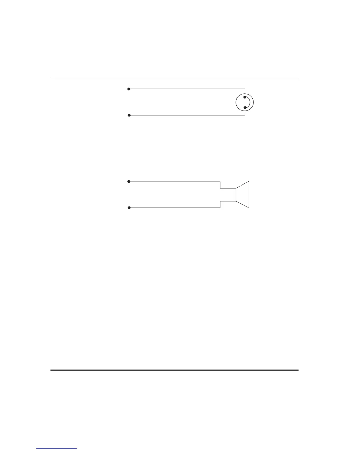
MECHANICAL
BELL
BELL OUTPUT
4 (–)
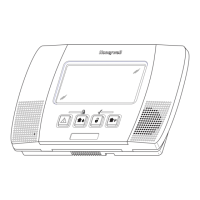
SIREN SUPERVISION (Self-Contained Siren/Speaker) - (Not for use in UL installations.) To
meet the NFPA 72 requirement program Question 12, Location 3, in Programming Submode 1 for
bell supervision. The siren is then supervised for an open circuit (not a short circuit) across the bell
output terminals; the keypad will indicate that a supervision condition has occurred and bell
supervision is reported to the CS, if enabled (Programming Submode 2, Question 43, Locations 1
and 2). If the siren is already sounding, the supervision will not take effect until after bell cutoff
time.
NOTE: Use FBII models ZR815C, ZR815EC, or ZR830EC. See the following diagram:
3 (+)
OMNI624-002-V0
SIREN/SPEAKER
BELL OUTPUT
4 (–)
5 — SIREN SUPERVISION INPUT: The Bell output may be supervised when a conventional bell or a
self-contained siren is connected. When connecting a conventional bell or a self-contained siren to
the bell output terminals (3 and 4), the jumper JP4 must be placed across pins 1 and 2. When
connecting an external siren driver to the bell output terminals, the supervision wire is connected to
the siren supervision terminal of the siren driver, and the jumper JP4 must be placed across pins 3
and 4. A supervisory condition will generate a pulsing keypad sounder. Also, the supervisory LED
on the keypad will pulse. The sounder may be silenced by entering a valid user code while the
system is disarmed. The LED will continue to pulse until the supervision is fixed. If a bell, self-
contained siren, or external siren driver is not connected to the bell output terminals, a 100-ohm
resistor must be placed across the siren supervision input to prevent a bell supervision error or you
must disable bell supervision (Programming Submode 1, Question 12, Location 3). Bell supervision
will be reported to the CS if CS code is enabled.
6 (+) & 7 (–) — SMOKE DETECTOR POWER (B+): This system will accept 9.5–12VDC 4-wire smoke
detectors only. Approximately 50mA of current is available at these terminals for powering all
detectors and/or an EOL relay. For UL installations, use a UL Listed smoke detector and see wiring
diagram for hookup.
These terminals adhere to the fire verification and reset logic, which is explained in the System
Programming section of this manual. The smoke detector power may be manually reset by clearing
the alarm memory and then entering a valid user code.
6 (+) & 4 (–) — REGULATED POWER (11.5 –13.1VDC B+): The total regulated output power for
motion detectors and other external devices is 500mA at 11.8 - 12.5V for residential applications, or
12.0 - 12.5V for commercial applications, with less than 100 mVPP ripple. The total regulated
output capacity of the control panel includes the power available from these terminals (6 and 4) as
 Loading...