11–2
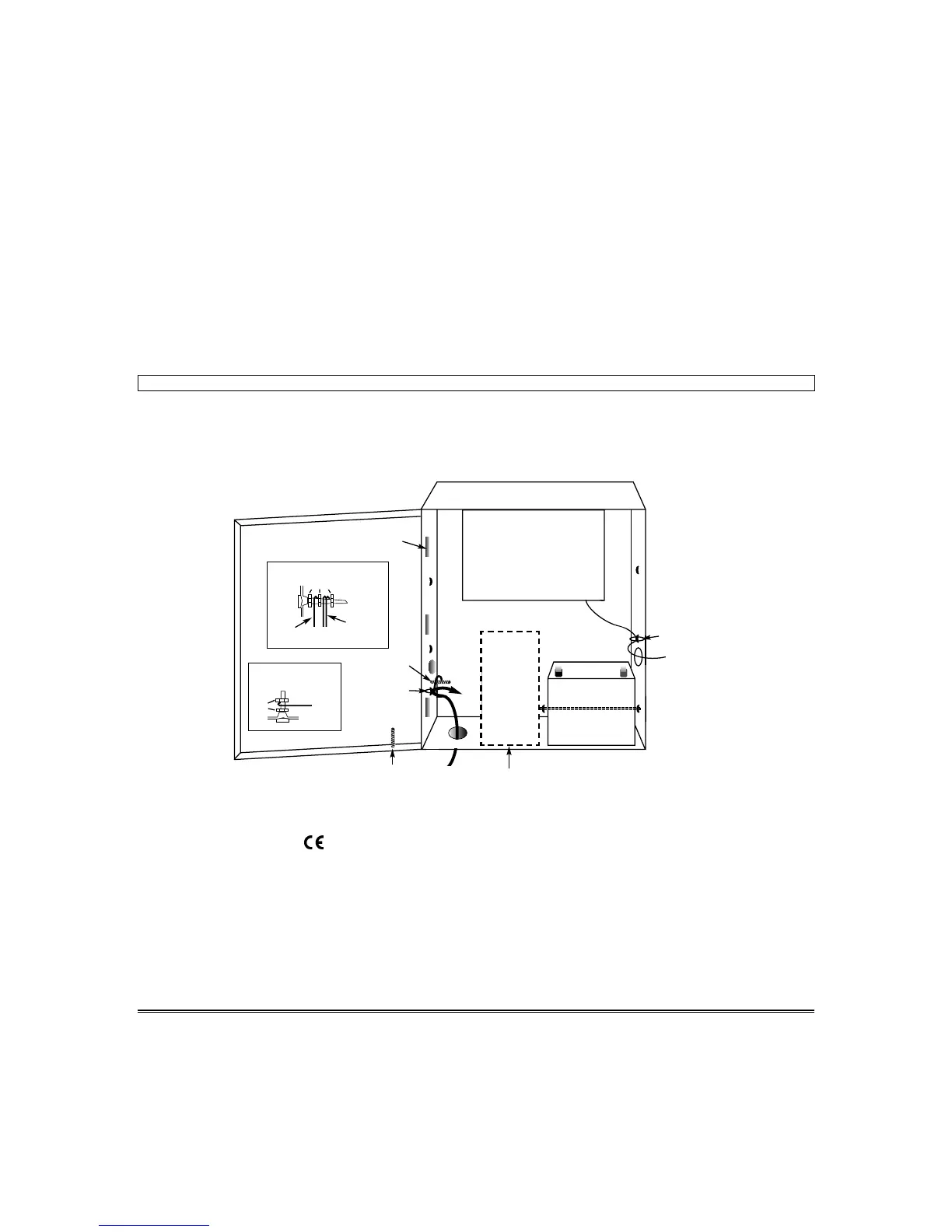
CABINET ASSEMBLY OVERVIEW
Mains and Transformer Wiring Connections
1. Connect the control panel’s AC input screw terminals to the transformer’s 12V secondary screw terminals.
2. Connect the incoming mains wires to the transformer’s 230V mains screw terminals.
Telephone and Low Voltage Wire Connections
1. Route the telephone wires into the control panel through the knockout on the right-hand sidewall of the cabinet.
Anchor these wires to the middle tie wrap loop on the right-hand sidewall using a supplied tie wrap.
2. Connect the telephone wires to the designated telephone terminals on the control panel PC board.
3. Anchor all low-voltage wiring to appropriate tie downs to prevent contact with the mains wiring.
IMPORTANT: Do not apply mains power until all wiring has been completed.
Mounting the Backup Battery
1. Mount the battery in the cabinet as shown in the Assembly Overview diagram.
2. Anchor the battery to the tie wrap loops as shown using tie wraps provided. This prevents the battery from
falling out of the cabinet if jarred.
CONTROL PANEL PCB
TIE WRAP WIRES
TO THIS LOOP
12V BATTERY
TELEPHONE
WIRES
BEND LOWER EDGE
OF HINGE TANGS
(3 PLACES)
TIE WRAP LOOPS
FOR ANCHORING
BATTERY
BACK BOX
GROUND SCREW
(SEE DETAIL A)
TIE WRAP WIRES
TO THIS LOOP
DETAIL A
DETAIL B
BACK BOX GROUND SCREW
Ground wires to
door and control
panel PCB
DOOR GROUND SCREW
Ground
Wire To
Back Box
Hex Nuts
Hex
Nuts
Incoming
Ground Wire
DOOR GROUND
SCREW
(SEE DETAIL B)
MAINS
AND
EARTH
GROUND
WIRES
TO
TERMS.
TRANSFORMER
LOCATION
O560 DECLARATION OF CONFORMITY
OMNI624 is in conformity with the essential requirements as described in Directive
1999/5/EC and satisfy all the technical regulations applicable to the product within
this directive
EN 50081-1:1992 EN 50130-4:1998 EN 60950:1992 TBR 21
This apparatus has been assessed for connection to the following circuits
Public Switched Telephone Networks (PSTN) -non DDI
Private Branch Exchange (PBX)
 Loading...