Applicator Interface Kit Installation Guide 11
Relay Out
The applicator card support 4 relay output ports. The relay of the OUT ports are
configured using the DC 5V and DC 24V settings. Relay 1 and Relay 3 are
configured by DC 5V setting and Relay 2 and Relay 4 are configured by DC 24V
setting. DC 5V and DC 24V settings are legacy applicator card settings, no
power is supplied by PX4IE/6IE applicator card. Any signals that are within the
max load breaking capacity of the relay can be connected to the relays.
Max AC Load Breaking Capacity
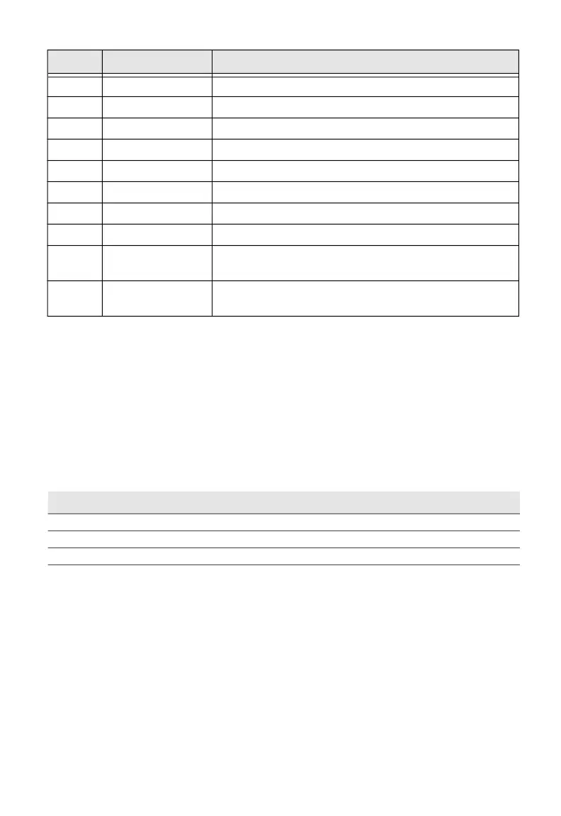
22 MediaOut_C Media Out Collector Opto Out Channel
7 MediaOut_E Media Out Emitter Opto Out Channel
37 RibbonOut_C Ribbon Out Collector Opto Out Channel
23 RibbonOut_E Ribbon Out Emitter Opto Out Channel
8 DataReady_C Data Ready Collector Opto Out Channel
38 DataReady_E Data Ready Emitter Opto Out Channel
24 VOID_C VOID Collector Opto Out Channel
9 VOID_E VOID Emitter Opto Out Channel
39 RTWOUTEXT_C External output signal for Ready-to-Work
Indicator Collector Opto Out Channel
25 RTWOUTEXT_E External output signal for Ready-to-Work
Indicator Emitter Opto Out Channel
Signal Description Max.
I Current 1A
Psw AC Switching power 100VA AC
Vsw AC Switching voltage 100V AC
Pin Signal Description
 Loading...