8 Applicator Interface Kit Installation Guide
Applicator Interface IN Signals
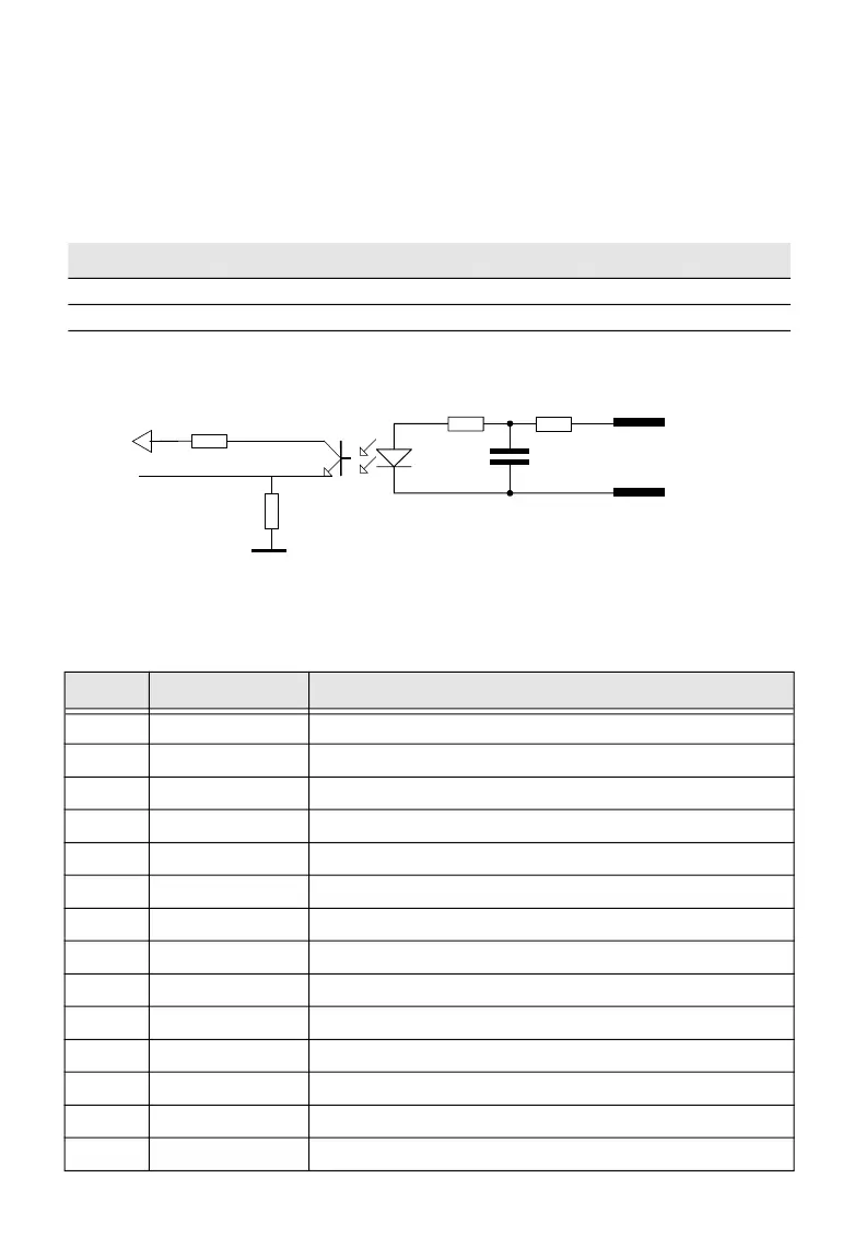
The Applicator Interface supports 8 digital input ports with optocouplers. All in
signals are asserted by setting the pin LOW and de-asserted by setting the pin
HIGH.
IN Signals Specification
Simplified schematic of a digital IN port
IN Signals Connector Configuration
Signal Description Min. Typical Max.
Vin [High] Input Voltage High 10V 24V 40V
Vin [Low] Input Voltage Low -1V 0V 1V
Pin Signal Description
10 StartPrint_K Start print Anode Opto In Channel
40 StartPrint_A Start print Cathode Opto In Channel
26 Feed_A Feed Anode Opto In Channel
11 Feed_K Feed Cathode Opto In Channel
41 Pause_A Pause Anode Opto In Channel
27 Pause_K Pause Cathode Opto In Channel
12 Reprint_A Reprint Anode Opto In Channel
42 Reprint_K Reprint Cathode Opto In Channel
28 AppErr1_A Applicator Error 1 Anode Opto In Channel
13 APPErr1_K Applicator Error 1 Cathode Opto In Channel
43 AppErr2_A Applicator Error 2 Anode Opto In Channel
29 APPErr2_K Applicator Error 2 Cathode Opto In Channel
14 AppErr3_A Applicator Error 3 Anode Opto In Channel
44 APPErr3_K Applicator Error 3 Cathode Opto In Channel
 Loading...