Applicator Interface Kit Installation Guide 25
Port Pintout Mapping for Applicator Interface
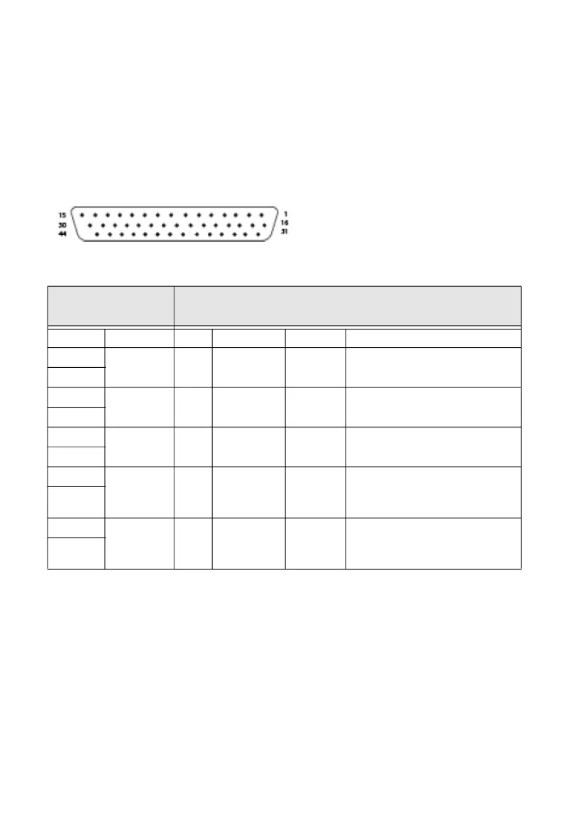
The Physical connectors of the Z, S style connectors and the External Error port
connector pins are mapped to the 44-pin connector of the applicator interface
option board.
The mapping of the applicator interface ports are detailed below.
DB-44 Connector Pin
Applicator
Interface (44 pin)
External Error Port (8 pin)
Pin Type Pin Signal Type Description
28 Input 1 AppErr_1 Input Applicator error#1
13
43 Input 2 AppErr_2 Input Applicator error#2
29
14 Input 3 AppErr_3 Input Applicator error#3
44
30 Input 4 AppErr_4 Input Honeywell Ready-to-Work
indicator input for external
errors (RtW_In_Ext)
15
39 Output 6 RTW_Out Output Honeywell Ready-to-Work
indicator output for total
system indicator
25
 Loading...