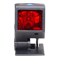
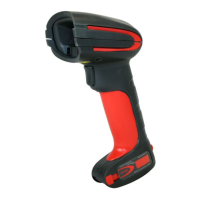
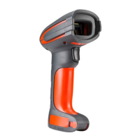
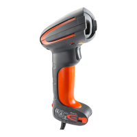
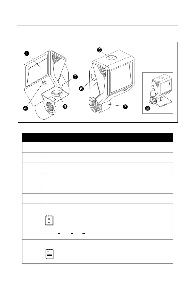
EasyManuals Logo

Honeywell QuantumT MS3580 User Manual

Honeywell QuantumT MS3580
61 pages
To Next Page IconTo Next Page
To Previous Page IconTo Previous Page
Page #9 background imageLoading...
Page #9 background image
4
INTRODUCTION
Scanner Components
Figure 1. Scanner Components
ITEM NO.
DESCRIPTION
1 Red Output Window (Laser Aperture)
2 Pin Hole for Cable Release
3 10-Pin RJ45, Female Socket
4 Speaker
5 Blue and White LED Indicators
6 Button
7
Protective Boot and Stand Connection
Never remove the protective boot from the MS3580.
Removing the protective boot will expose electrical
components of the scanner that are highly susceptible to
e
lectrostatic discharge (ESD).
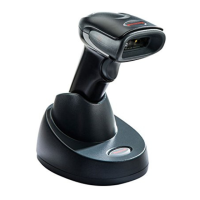
8
Pedestal Stand
The type of stand provided is dependent on the specific
MS3540 kit purchased.

Questions and Answers:

Question and Answer IconNeed help?

Do you have a question about the Honeywell QuantumT MS3580 and is the answer not in the manual?

Honeywell QuantumT MS3580 Specifications

General IconGeneral
BrandHoneywell
ModelQuantumT MS3580
CategoryScanner
LanguageEnglish

Related product manuals