20
MAN0530 Issue 09 October 03 Searchline Excel
2104M0506
3. INSTALLATION AND OPERATION
l. The 24V supply should be free from large transients and fluctuations.
m. The field cabling conductors should have sufficient cross sectional area to ensure that the minimum
supply voltage applied to the gas detector is 18V at a current of 420mA. This corresponds to a
maximum round loop impedance of 14 ohms for a nominal 24V system supply.
n. Receivers should not be installed in close proximity to the antennae of high powered
radio, radar and satellite communication equipment.
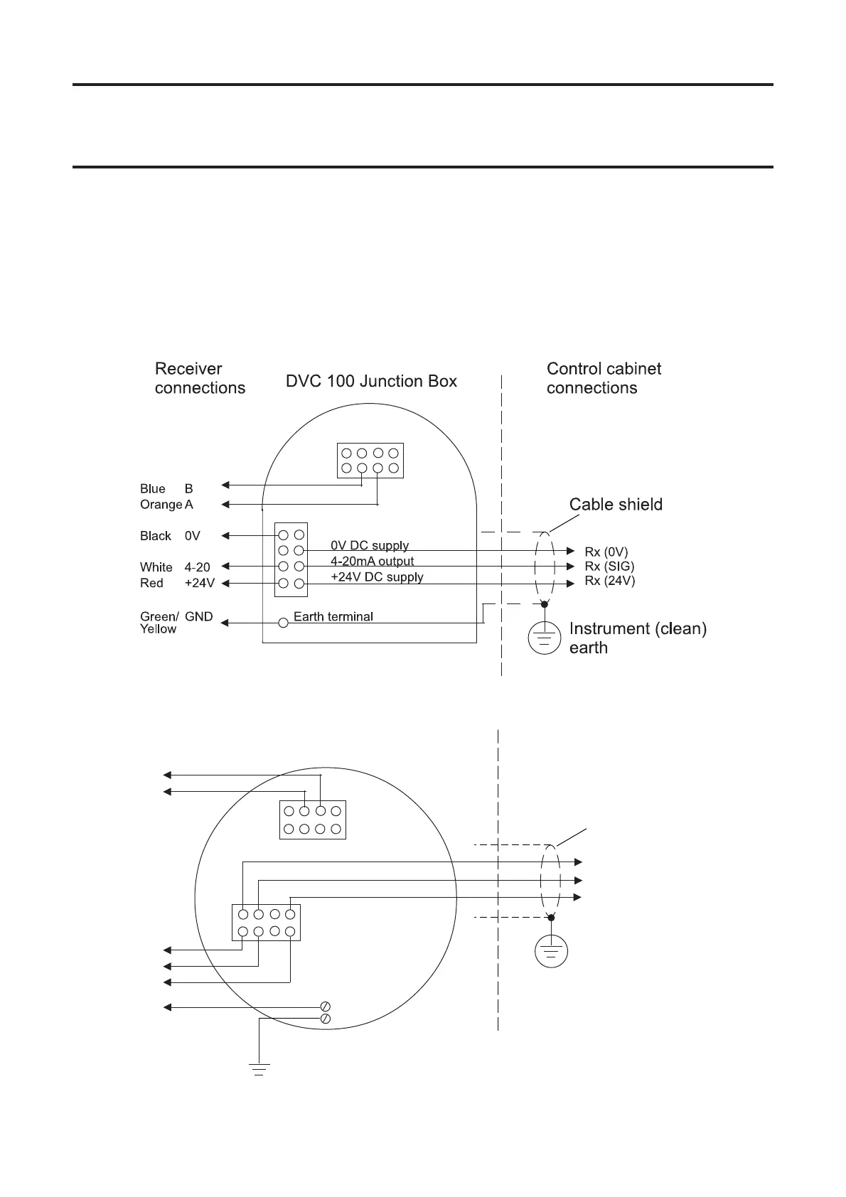
3.3.2 Receiver Connections via DVC100
3.3.3 Receiver Connections via DX100
>
+24V DC supply
4-20mA output
0V DC supply
Rx (0V)
Rx (SIG)
Rx (24V)
8
$&>
Instrument (clean)
earth
Cable shield
Blue B
Orange A
TB1
TB2
Green/ GND
Yellow
Red +24V
White 4-20
Black 0V
DX100 Junction Box
Receiver
connections
Control cabinet
connections
Safety/protective
ground
The earth bonding arrangement must ensure that the maximum peak voltage between
the unit case earth and any field cable conductor is less than 350V. Voltages in excess
of this can cause permanent damage to the unit’s RFI protection filters.
I.S. Barrier ground (CSA)
Earth terminal
 Loading...