21
MAN0530 Issue 09 October 03 Searchline Excel
2104M0506
3. INSTALLATION AND OPERATION
3.3.3 Receiver Connections via DX100 (M)
16
1
6
TB2
TB1
black (0V)
green/yellow (earth)
blue (B)
orange (A)
white (4-20mA)
red (+24VDC)
+24VDC in
Modbus A
4-20mA - out
Modbus B
Screen - Modbus Drain
0VDC - in
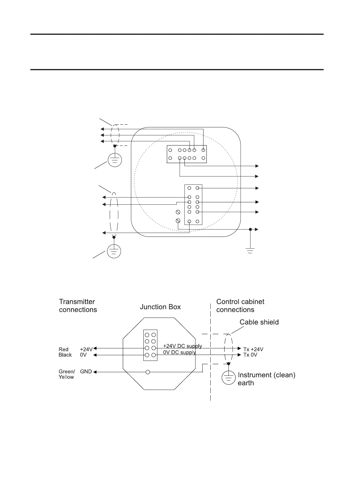
Cable shield
Instrument (clean)
earth
DX100 (M) Junction Box
Receiver
connections
Control cabinet
connections
Safety/protective
ground
Instrument (clean)
earth
Cable shield
The earth bonding arrangement must ensure that the
maximum peak voltage between the unit case earth
and any field cable conductor is less than 350V.
Voltages in excess of this can cause permanent
damage to the unit’s RFI protection filters.
3.3.4 Transmitter Connections
 Loading...