62
MAN0530 Issue 09 October 03 Searchline Excel
2104M0506
4. CROSS-DUCT EXCEL
4.4.1 Mechanical Installation
Verify that the equipment to be installed is correct for the type of installation required (i.e. short/
long range and normal/high temperature.)
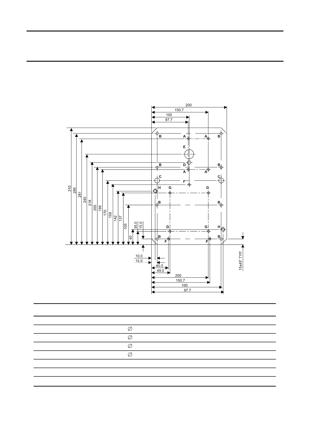
Identify the mounting holes using the following drawing and table:
Identity Quantity Size Used for
A4M6 tapped Mounting cell mounting
B8 6.5mm Mounting plate to support bar mounting
C2 14mm Clearance for support bar fixing nuts
D1 10mm Drain for mounting cell
E1 25mm Cross-Duct optical measurement path
F3M6 tapped DVC100 mounting
G4M6 tapped BARTEC terminal box fixing
H2M10 tapped DX100/DX100 (M) fixing
 Loading...