and low voltage circuits.
All circuits, except battery cables
and AC, are power limited.
Maintain at least 0.25” spacing
between power limited and non-
power limited circuits.
Separate high and low voltage
circuits.
Route all low voltage
wiring through any of
these knockouts.
Fire alarm power-limited circuits are
installed using types FPL, FPLR,
FPLP or permitted substitute cables,
provided these power-limited cable
conductors extending beyond the
jacket are separated by a minimum
of 0.25 in. (6.35 mm) or by a non-
conductive sleeve or non-conductive
barrier from all other conductors.
battery cables
from under board
AC Power
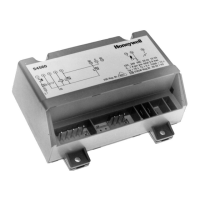
5895XL Board
Figure 3.2 Wire Routing Example
red black
Note: Board assembly shown without
Formex cover for illustration purposes
only. Formex cover must be used in all
installations.

 Loading...