November 2018 Quick Start Installation Guide 3
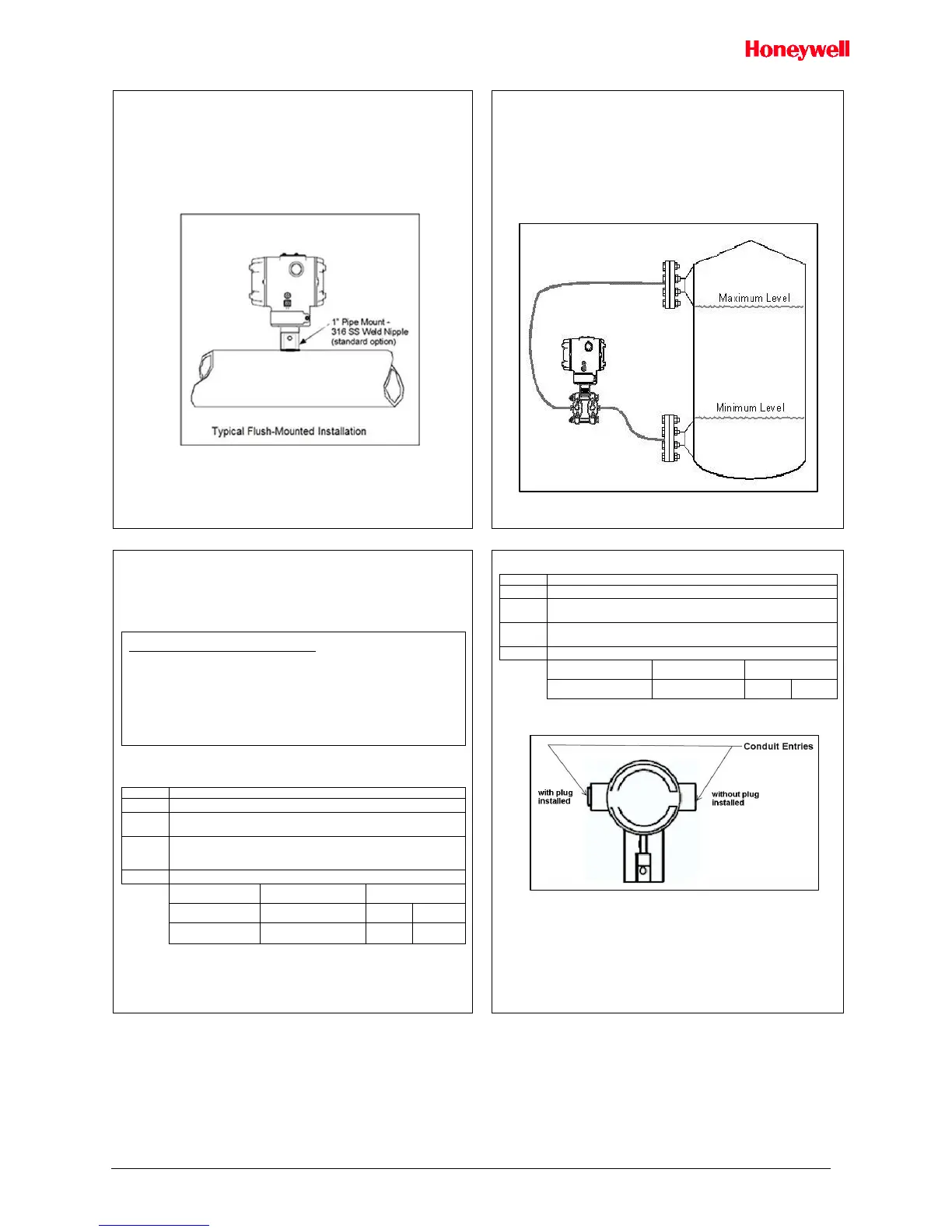
Flush Mounting
To mount a flush mounted transmitter model, cut a hole for a 1-inch standard pipe in the
tank or pipe where the transmitter is to be mounted. See Figure 7.
Weld the 1-inch mounting sleeve to the wall of the tank or to the hole cut on the pipe.
Insert the meter body of the transmitter into the mounting sleeve and secure with the
locking bolt. Tighten the bolt to a torque of 6.4Nm ±0.30Nm [4.7ft.-lbs. ±0.2ft.-lbs.]
Once the transmitter is mounted, the transmitter housing can be rotated to the desired
position. See Figure 7.
Figure 7: Flush Mounting
Remote Seal Mounting
Mount the transmitter at a remote distance determined by length of capillary tubing.
Note: The combination of tank vacuum and high pressure capillary head effect should
not exceed 9psi (300mm Hg) absolute.
On insulated tanks, remove enough insulation to accommodate the mounting sleeve.
Figure 8 Example – Typical Remote Seal Transmitter installation.
Note: For Sanitary 3-A installations, only mount the transmitter outside of the Non-
Product Contact area where incidental contact with the process material is unlikely,
use a minimum capillary length of 1.5m (5ft.)
Figure 8: Remote Seal mounting
Conduit Entry Plugs and Adapters
Procedures
It is the User/Installer’s responsibility to install the Transmitters in accordance with
national and local code requirements. Conduit entry plugs and adapters shall be
suitable for the environment, shall be certified for the hazardous location when required
and acceptable to the authority having jurisdiction for the plant.
CONDUIT ENTRY PRECAUTIONARY NOTICE
THE CONDUIT/CABLE GLAND ENTRIES OF THIS PRODUCT ARE SUPPLIED
WITH PLASTIC DUST CAPS WHICH ARE NOT TO BE USED IN SERVICE.
IT IS THE USER’S RESPONSIBILITY TO REPLACE THE DUST CAPS WITH
CABLE GLANDS, ADAPTORS AND/OR BLANKING PLUGS WHICH ARE
SUITABLE FOR THE ENVIRONMENT INTO WHICH THIS PRODUCT WILL BE
INSTALLED. THIS INCLUDES ENSURING COMPLIANCE WITH HAZARDOUS
LOCATION REQUIREMENTS AND REQUIREMENTS OF OTHER GOVERNING
AUTHORITIES AS APPLICABLE.
Use the following procedures for installation:
Table 1 - Conduit Entry Plugs
Remove the protective plastic cap from the threaded conduit entry.
To ensure the environmental ingress protection rating on tapered
threads (NPT), a non-hardening thread sealant may be used.
Thread the appropriate size conduit plug (M20 or ½” NPT) into the
conduit entry opening. Do not install conduit entry plugs in conduit entry
openings if adapters or reducers will be used.
Tighten adapters according to the following table.
Table 2 - Conduit Adapters
Remove the protective plastic cap from the threaded conduit entry.
To ensure the environmental ingress rating on tapered threads (NPT),
a non-hardening thread sealant may be used.
Thread the appropriate size adapter (M20 or ½ NPT) into the conduit
entry opening
Tighten adapters according to the following table.
Figure 9: Electronic Housing Conduit Entries
Note. No plugs come installed in the housings. All housings come with temporary
plastic dust protectors (red) installed and are not certified for use in any installation

 Loading...


