November 2018 Quick Start Installation Guide 4
Wiring Connections and Power Up
Summary
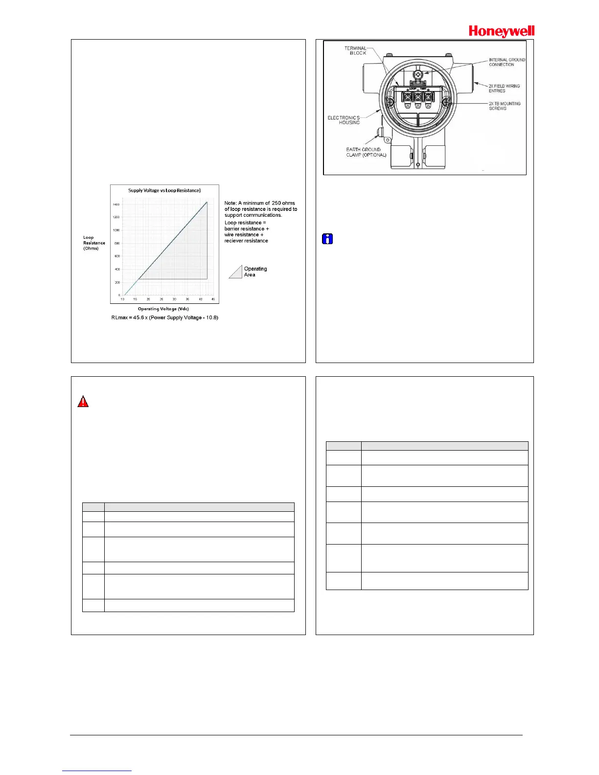
The transmitter is designed to operate in a two-wire power/current loop with loop
resistance and power supply voltage within the operating range shown in Figure 10
Figure 10
Loop wiring is connected to the transmitter by simply attaching the positive (+) and negative
(–) loop wires to the positive (+) and negative (–) SIGNAL screw terminals on the terminal
block in the transmitter’s electronics housing shown in Figure 11.
Each transmitter includes an internal terminal to connect it to earth ground. Also, a ground
terminal can be optionally added to the outside of the electronics housing. While it is not
necessary to ground the transmitter for proper operation, doing so tends to minimize the
possible effects of noise on the output signal and affords protection against lightning and
static discharge.
An optional lightning terminal block can be installed in place of the non-lightning terminal
block for Transmitters that will be installed in an area that is highly susceptible to lightning
strikes.
Figure 10: Two-wire power/current loop
Figure 11: Terminal Block and Grounding Screw location
Wiring Variations
The above procedures are used to connect power to a Transmitter. For loop wiring
and external wiring, detailed drawings are provided for Transmitter installation in
non-intrinsically safe areas and for intrinsically safe loops in hazardous area locations.
This procedure shows the steps for connecting power to the transmitter.
Wiring must comply with local codes, regulations and ordinances. Grounding
may be required to meet various approval body certification, for example CE
conformity. Refer to the ST 700 SmartLine Transmitter User’s Manual,
Documents # 34-ST-25-44 for details.
Explosion-Proof Conduit Seal
When installed as explosion proof in a Division 1 Hazardous Location, keep covers
tight while the Transmitter is energized. Disconnect power to the Transmitter in the
non-hazardous area prior to removing end caps for service.
When installed as non-incendive equipment in a Division 2 hazardous location,
disconnect power to the Transmitter in the non-hazardous area, or determine that the
location is non-hazardous before disconnecting or connecting the Transmitter wires.
Transmitters installed as explosion proof in Class I, Division 1, Group A Hazardous
(classified) locations in accordance with ANSI/NFPA 70, the US National Electrical Code,
require a LISTED explosion proof seal to be installed in the conduit, within 18 inches
(457.2mm) of the Transmitter. Crouse-Hinds type EYS/EYD or EYSX/EYDX are examples
of LISTED explosion proof seals that meet this requirement. Transmitters installed as
explosion proof in Class I, Division 1, Group B, C or D hazardous (classified) locations do
not require that explosion proof seal be installed in the conduit.
See Figure 11, above, for parts locations.
Remove the end cap cover from the terminal block end of the Electronics
Housing
Feed loop power leads through one end of the conduit entrances on
either side of the Electronics Housing. The Transmitter accepts up to 16
AWG wire.
Plug the unused conduit entrance as specified in Table 1.
Connect the positive loop power lead to the positive (+) terminal and the
negative loop power lead to the negative (-) terminal. Note that the
Transmitter is not polarity-sensitive.
Replace the end cap, and secure it in place using a 1.5mm hex wrench.
Trim the Transmitter
Procedure to Trim the Transmitter
For a transmitter with a small differential pressure span, you must ensure that the
transmitter is vertical when mounting it. You do this by leveling the transmitter side-
to-side and front-to-back. See Figure 5 for suggestions on how to level the
transmitter using a spirit balance. You must also zero the transmitter by following
the steps in this table.
Attach the transmitter to the mounting bracket but do not
completely tighten the mounting bolts
Connect a tube between the input connections in the high
pressure (HP) and low pressure (LP) heads to eliminate the
effects of any surrounding air currents.
Connect 24Vdc power to the transmitter. Connect a digital
voltmeter to monitor the PV output.
Use applicable communicator to establish communications with
the transmitter. For HART, use MCT or other HART
Communicator with applicable Honeywell DD's.
While reading the transmitter’s output on a communication tool
or a voltmeter, position the transmitter so the output reading is
at or near zero, and then completely tighten the mounting bolts.
The Local Display or applicable communicator can be used to
perform the Zero Corrects. This corrects the transmitter for any
minor error that may occur after the mounting bolts are
tightened.
Remove the tube from between the input connections, the
power, and the digital voltmeter or communication tool.

 Loading...


