November 2018 Quick Start Installation Guide 2
Existing Mounting Bracket
Align appropriate mounting holes in transmitter with holes in bracket and secure with
bolts and washers provided.
Note: If the meter body is hexagonal, you must use the additional bracket supplied.
If meter body is round, discard the bracket.
Example – LGP model transmitter mounted to optional angle mounting bracket.
DP, Dual Head GP, Dual Head AP
and DP Remote Seals.
Use alternate mounting holes in end of
heads.
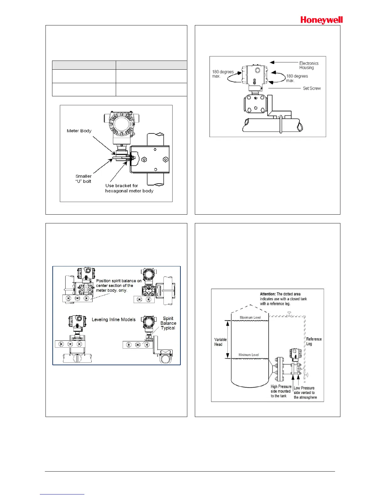
In-line GP and AP (LGP model) or
GP/AP Remote Seal
Use smaller “U” bolt provided to attach
meter body to bracket. See Figure 3.
Figure 3: LGP and LAP models
Rotating Transmitter Housing
Loosen set screw on outside neck of transmitter one full turn. Rotate Transmitter
housing in maximum of 180 degree increment in left or right direction from center to
position you require and tighten set screw (1.46 to 1.68Nm/13 to 15lb-in).
Figure 4 Example – Rotating Transmitter Housing.
Figure 4: Rotating Transmitter Housing
Leveling Transmitters with Small Absolute or Differential Pressure
Spans
Mounting position of these transmitters is critical due to the smaller transmitter spans.
To minimize these positional effects on calibration (zero shift), take the appropriate
mounting precautions that follow for the given transmitter model.
See Figure 5 for suggestions on how to level the transmitter using a spirit balance.
To perform a Zero Trim after leveling, refer to Trim the Transmitter on page 4.
Figure 5: Using level to mount transmitter
For transmitter models STA725 and STA72S you must ensure that the transmitter is
vertical when mounting it. You do this by leveling the transmitter side-to-side and
front-to-back.
Mount transmitter vertically to assure best accuracy. Position the spirit balance on the
pressure connection surface of AP body.
Flange Mounting
To mount a flange mounted transmitter model, bolt the transmitter’s flange to the flange
pipe on the wall of the tank.
On insulated tanks, remove enough insulation to accommodate the flange extension.
It is the End User’s responsibility to provide a flange gasket and mounting hardware that
are suitable for the transmitter’s service condition.
To prevent degradation of performance in Flush-Mounted Flanged Transmitters,
exercise care to ensure that the internal diameter of the flange gasket does not obstruct
the sensing diaphragm.
To prevent degradation of performance in Extended Mount Flanged Transmitters,
ensure that there is sufficient clearance in front of the sensing diaphragm body.
Figure 6: Flange mounting

 Loading...


