November 2018 Quick Start Installation Guide 5
Set the Jumpers For HART
Setting Failsafe Direction and Write Protect Jumpers
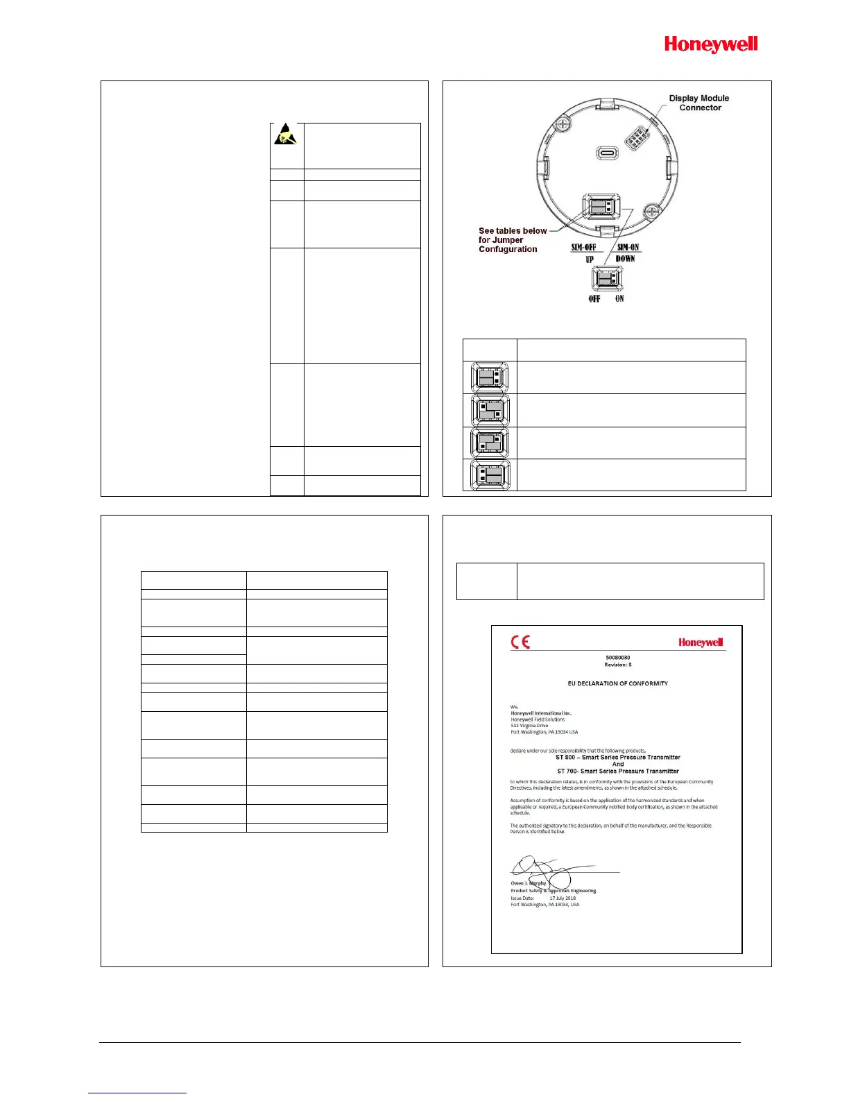
Figure 12: Jumper Location HART
Table 3 - Jumper Settings
Failsafe = UP (High)
Write Protect = OFF (Not Protected)
Failsafe = DOWN (Low)
Write Protect = OFF (Not Protected)
Failsafe = UP (High)
Write Protect = ON (Protected)
Failsafe = DOWN (Low)
Write Protect = ON (Protected)
The ST 700 Basic SmartLine Pressure
Transmitter provides two jumpers to set
the desired failsafe action and Write
Protect option.
See, Figure 12 and Table 3
The top jumper on the electronics module
sets the Failsafe direction. The default
setting is up-scale failsafe.
Up Scale drives the loop to a value greater
than 21.5mA while Down Scale drives the
loop to a value less than 3.6mA.
You can change the failsafe direction by
moving the Failsafe Jumper (top jumper)
to the desired position (UP or DOWN).
The bottom jumper sets the Write Protect.
The default setting is OFF (Unprotected).
When set to the ON (Protected) position,
Changed configuration parameters cannot
be written to the transmitter.
When set to the OFF (Unprotected)
position, Changed configuration
parameters can be written to the
transmitter.
ATTENTION: Electrostatic
Discharge (ESD) hazards.
Observe precautions for
handling electrostatic sensitive
devices
Turn OFF Transmitter power.
Loosen the end-cap lock, and
unscrew the end cap from
the Electronics side of the
Transmitter housing.
If applicable, carefully
depress the tabs on the sides
of the Display Module and
pull it off.
If necessary, move the
interface connector from the
Communication Module to
the display module to provide
the preferred orientation of
the display module in the
window.
Set the Failsafe Jumper (top
jumper) to the desired action
(UP or DOWN). And the
Write Protect jumper (Bottom
jumper) to the desired
behavior (Protected or
Unprotected) See Table for
jumper positioning.
Screw on the end cap and
tighten the end-cap lock.
Turn ON Transmitter power.
Configuration Guide
The ST700 Basic SmartLine Pressure transmitter has only one display options:
Standard LCD Display: 2 lines, 6 character
Table 4 - Standard Display Menu
Pressure Units [2UNITS]
(Visible for all PV except
Flow)
Always used when PV is flow
Enter LRV [6ENTLRV]
Enter URV [7ENTURV]
Only if extended Menu is enabled
Only if extended Menu is enabled
Loop Test [11LPTEST]
Loop Test
Only if extended Menu is enabled
Set LRV
[12SETLRV]
Set URV [13SETURV]
Only if extended Menu is enabled
Only if extended Menu is enabled
Enable Extended Menu
[EXDMNU ]
Appendix A. PRODUCT CERTIFICATIONS
Safety Instrumented Systems (SIS) Installations
For Safety Certified Installations, please refer to ST 800 & ST 700 Safety Manual
34-ST-25-37 for installation procedure and system requirements.
IEC 61508 SIL 2 for non-redundant use and SIL 3 for redundant
use according to EXIDA and TÜV Nord Sys Tec GmbH & Co. KG
under the following standards: IEC61508-1: 2010; IEC 61508-2:
2010; IEC61508-3: 2010.
A2. European Directive Information (CE Mark)

 Loading...


