SPM Single Point Monitor
SPM Technical Handbook
2-4
2.3.4 Hydrogen Sulfide (H
2
S) Scrubber
Filter
Hydrogen Sulfide Scrubber Filters (P/N 1295K0497)
remove H
2
S from the sample stream. H
2
S can cross-
interfere when monitoring for gases detected on the
Hydrides, XP Hydrides, or the Hydrogen Cyanide
Chemcassettes. Install the H
2
S Scrubber Filter in the
sample line as close to the instrument as possible to
permit easy access for visual inspection and replacement
of the filter.
2.3.5 Exhaust Line
The exhaust port (24) uses 3/16” I.D. x 1/4” O.D.
polypropylene tubing.
To install exhaust tubing, push the end of the tube into
the exhaust port (24) until it seats fully inside the fitting
body. To release the tubing, push the small gray collar
in while pulling the tubing out.
Exhaust line length may be up to 10 feet long. Also, make
sure the exhaust line is vented properly.
Sample inlet and exhaust outlet tubing is supplied with
the instrument.
2.3.6 High Pressure Locations
Monitoring in a location with a pressure higher than
that of ambient levels may cause sample gas to be
forced into the instrument and surrounding air during
Chemcassette
®
advancement. Additional parts are
required. Please contact Honeywell Analytics for
application assistance.
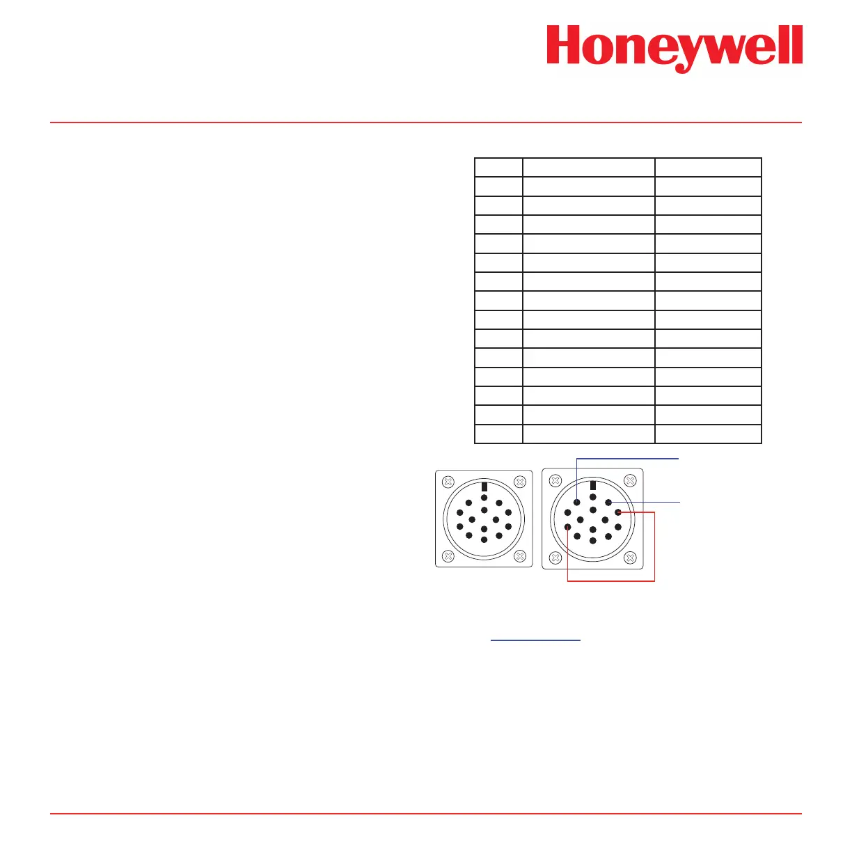
2.4 SPM Output Connections
The gas alarm relays, instrument fault relay, and 4-20 mA
output contacts are wired to a 14-pin circular connector
(3). The pin designations are as listed in Section 2.4.1.
2.4.1 Output Pin Designations
Pin Designation Conditions
A Instrument Fault Normally Open
B Instrument Fault Common
C Instrument Fault Normally Closed
D Gas Alarm 1 Normally Closed
E* Remote Reset Option
F Gas Alarm 1 Common
G Gas Alarm 1 Normally Open
H** 4-20 mA (+)
J Ground
K** 4-20 mA (-)
L Gas Alarm 2 Normally Closed
M Gas Alarm 2 Common
N* Remote Reset Option
P Gas Alarm 2 Normally Open
A
B
C
D
E
F
G
H
J
K
L
M
N
P
A
B
C
D
E
F
G
H
J
K
L
M
N
P
4-20mA -
4-20mA +
Signal to/from HA controllers or PLC
Jumper wire from pin “H” to pin “C”
* Pins E and N will be open (i.e., no connection) except
on instruments fitted with the Remote Reset option.
See Section 5.10 for more information.
** Do not connect analog devices with more than
850 ohm impedance.
Note:
The mA range is 4-20mA and does not indicate when
the unit is in a Fault condition. To receive a fault
indication on the mA output loop the 4-20 mA ‘+’
signal (H) through the Instrument Fault Common (B)
and use the Instrument Fault Normally Closed (C) as
your 4-20 mA ‘+’ signal. (See above for diagram)
 Loading...