SPM Single Point Monitor
SPM Technical Handbook
4-2
4.1 General Instrument Specifications
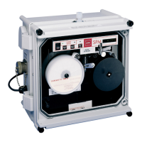
Alarm Settings Standard calibrations are factory set at 1/2
and 1 times TLV of the target gas for all gases
except Diisocyanates (5 ppb or 20 ppb). Gas
and alarm levels are indicated on the faceplate
of the instrument or on the ChemKey.
Detection Technique Chemcassette
®
Detection System
Alarm Indications Audio and visual alarms; SPDT relay
contacts.
Voltage 100 VAC to 240 VAC 50/60 Hz (+/- 10%) (Line
powered units; voltage-specific chargers
supplied with battery backup and portable
units.)
Voltage (battery unit) 12 VDC @ 5.4 Ah
Power 15 Watts for base unit. Fitted options may
change power requirements. (Consult
Honeywell Analytics)
Power (battery unit) 12 VDC @ .4A
Installation Category
(overvoltage)
II
Fuse Type 5 x 20 mm slo-blo
Fuse Rating Fuse rating may vary depending upon tted
options. See label next to fuse holder on front
panel.
Relay Rating 120 VAC 10A; 240 VAC 5A; 48 VDC 5A
Analog Output Isolated 4-20 mA. Maximum load 850 ohms.
Nominal Dimensions 30.5 x 30.5 x 17.8 cm [12”(H) x 12”(W) x 7”(D)]
Actual dimensions depend on tted options.
Weight 6.8 kg (15 pounds) to 11.4 kg (25 pounds).
Weight will vary depending on tted options.
Operating
Temperature Range
0 to 40°C (32 to 104°F)
(Temperature-compensating options
available)
Maximum sample
draw against vacuum
1 in/Hg
4.2 4-20 mA Output Signal
The 4-20 mA output on the SPM is always active during
monitoring. It is updated at the end of each analysis
period; as a result, the signal sent to the strip chart
recorder or other equipment is delayed by one analysis
period.
The 4-20 mA output is held at the last reported
concentration value until it is updated at the end of the
next sample period, even if an alarm condition has been
reset. This provides a more accurate calculation of time
weighted averages.
The 4-20 mA output is an isolated linear signal with 4.0
mA representing a concentration value of 0 and 20.0
mA representing a full scale concentration (generally
three times TLV).
4.3 Verifying the 4-20 mA Output Signal
To verify a proper 4-20 mA signal, perform the response
verification procedure as explained in Section 1.8. A
successful response test will generate an analog signal
ranging from 10.1 to 13.2 mA.
If the output is not within these limits, check the
following:
1. Check the integrity of all connections.
2. Check that the analog device is set for the proper
range.
3. Check that the impedance of the analog device
does not exceed 850 ohms.
If the problem still exists, consult Honeywell Analytics.
Note:
Pressing the alarm test key (10) will not cause the
4-20 mA output to change. See Section 1.7.3 for
information on how the 4-20 mA responds.
 Loading...