SPM Single Point Monitor
SPM Technical Handbook
3-2
3.1 Routine Maintenance Schedule
Three items of routine maintenance apply to all
systems:
• Replacing Chemcassettes
®
• Verifying system response
• Replacing the three internal filters annually
If there are external sample line filters, replace filters as
indicated in Section 4.11.
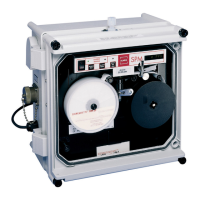
3.2 Chemcassette
®
Replacement
With no target gas present, the SP size Chemcassettes
®
require replacement every two weeks. EP size
Chemcassettes
®
require replacement every 30 days.
XP Chemcassettes
®
require replacement every 90 days.
See Section 1.5 for information on Chemcassette
®
replacement.
3.3 Verify System Response
Perform the verification routine every two to four weeks.
See Section 1.8 for more information.
3.4 Replacing Internal Filters
Internal filters should be replaced annually. The
replacement procedure will take approximately one
hour to perform. Follow these steps to replace internal
filters properly:
1. Separate cover/collar from body. Follow steps
in Section 2.5.
2. Open unit. Filters are located inside center
area of cover/collar, below and partially behind
printed circuit board (PCB). See illustration on
Page 5-5.
3. Remove the three screws and six fiber washers
securing the PCB. Note location of fiber washers
for re-assembly.
4. Leave all cables connected except J-11 (4
pin) and J-3 (10 pin) located on top right of
component side (rear view).
5. Carefully lift outward on PCB to locate J-11 (also
located to right on component side).
6. Support PCB temporarily in a “raised” position
using a rubber band.
7. Remove acid scrubber filter, mounted vertically
(Illustration item #66 on Page 5-5). Replace with
new filter (P/N 710235).
8. Remove particulate filter (Illustration item #65
on Page 5-5). Replace with new filter (P/N
780248).
Note:
Arrow on body of lter must point in right
direction .
9. Remove filter assembly (Illustration item #67 on
Page 5-5), if installed. Replace with new filter
(P/N 871134).
10. Verify that there are no kinks in tubing.
11. Remove temporary support from PCB.
12. Reconnect cables.
Caution
When reconnecting J-3, make sure opposite end
of cable is still connected. Check all other cable
connections on and near PCB.
13. Secure PCB with screws and fiber washers. Fiber
washers should be on both sides of PCB at each
screw location.
 Loading...