SPM Single Point Monitor
SPM Technical Handbook
4-6
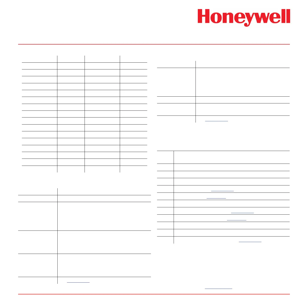
Table 4-1. mA Output for LDL
Gas mA at LDL Gas mA at LDL
DMA Low 4.25 GeH
4
(XPS) 7.76
DMA 5.07 H
2
Se 6.13
MDA 4.82 H
2
Se (XPS) 6.13
TDA 5.07 SbH
3
5.07
TDMAT 5.07 TBA 5.63
HDI 4.25 TBA (XPS) 5.63
N
2
H
4
5.07 TBP 5.63
MMH Low 5.63 TBP (XPS) 5.63
UDMH Low 6.70 H
2
S Low 4.19
AsH
3
5.63 HCI Low 4.38
AsH
3
(XPS) 5.07 HF 5.07
B
2
H
6
5.63 Cl
2
Low (XPS) 5.07
BF
3
Low 5.07 O
3
5.63
Si
2
H
6
5.63 ClO
2
(F
2
/Ox) 5.63
SiH
4
(XPS) 4.34 NH
3
(XPS) 4.31
GeH
4
7.76 SO
2
5.07
4.5 Status Indicators
Condition Indicator Status
Normal Monitoring Green system status LED (9) lighted.
Chemcassette
®
Loading
Green system status LED (9) ashing slowly. If
instrument remains in this mode for more than 2
minutes, red system status LED (12) will also begin to
ash, audio alarm pulses and the instrument fault relay
is activated.
Response Verication Green system status LED (9) ashing rapidly. If system
passes test, alarm lamp (16) lights and audio alarm
sounds continuously; if system fails test, red system
status LED (12) lights and audio alarm signals twice.
Instrument
Fault (except
Chemcassette
®
loading fault)
Red and green system status LEDs (9) and (12) are
both ashing. The relay disable LED (13) ashes
(except for the open tape load lever fault), audio alarm
pulses and the instrument fault relay is activated.
Gas Condition See Section 1.9.1.
4.6 Display Messages
Status Display
Normal Monitoring Actual concentration in ppm (parts-per-million) or ppb
(parts-per-billion). When unit detects an above full-
scale condition, the display will show xxx + ppx; e.g.,
AsH3 above full-scale is 150 + ppb; CI2 reading above
full-scale is 3.0 + ppm.
Verify Mode (VERIFY)
Instrument Fault (FAULT) (along with two-digit code; see Section 4.7 for
codes and corresponding faults or errors)
Alarm Simulation See Section 1.7.5 for displayed information.
4.7 Fault Codes
Instrument Fault or Error:
Message (FAULT) along with two-digit fault code
Fault
Code
Fault or Error
06 RAM Failure, Contact Honeywell Analytics
08 EEPROM Fault, Contact Honeywell Analytics
10 Look-up Table Error, Contact Honeywell Analytics
11 ChemKey Error (See Section 5.4.9)
17 Loss of Flow (See Section 3.8 Numbers 5, 6 & 7)
21 Motor Home Time-out, Contact Honeywell Analytics
25 Gate Fault (Mode Time-out) (See Section 1.8.2)
30 High Background Counts (See Section 3.8 No. 3)
32 Reference Voltage #1 Fault, Contact Honeywell Analytics
34 Battery Very Low
36 Over Temp (Heater Option Only) (See Section 5.9.3)
Contact Honeywell Analytics if problems persist.
Note:
A fault condition will cancel the alarm relay
disable feature. To resume operations with
alarm relay disabled, you must re-select the
feature. See Section 1.11.
 Loading...