SPM Single Point Monitor
SPM Technical Handbook
5-5
15
21
20
22
313029
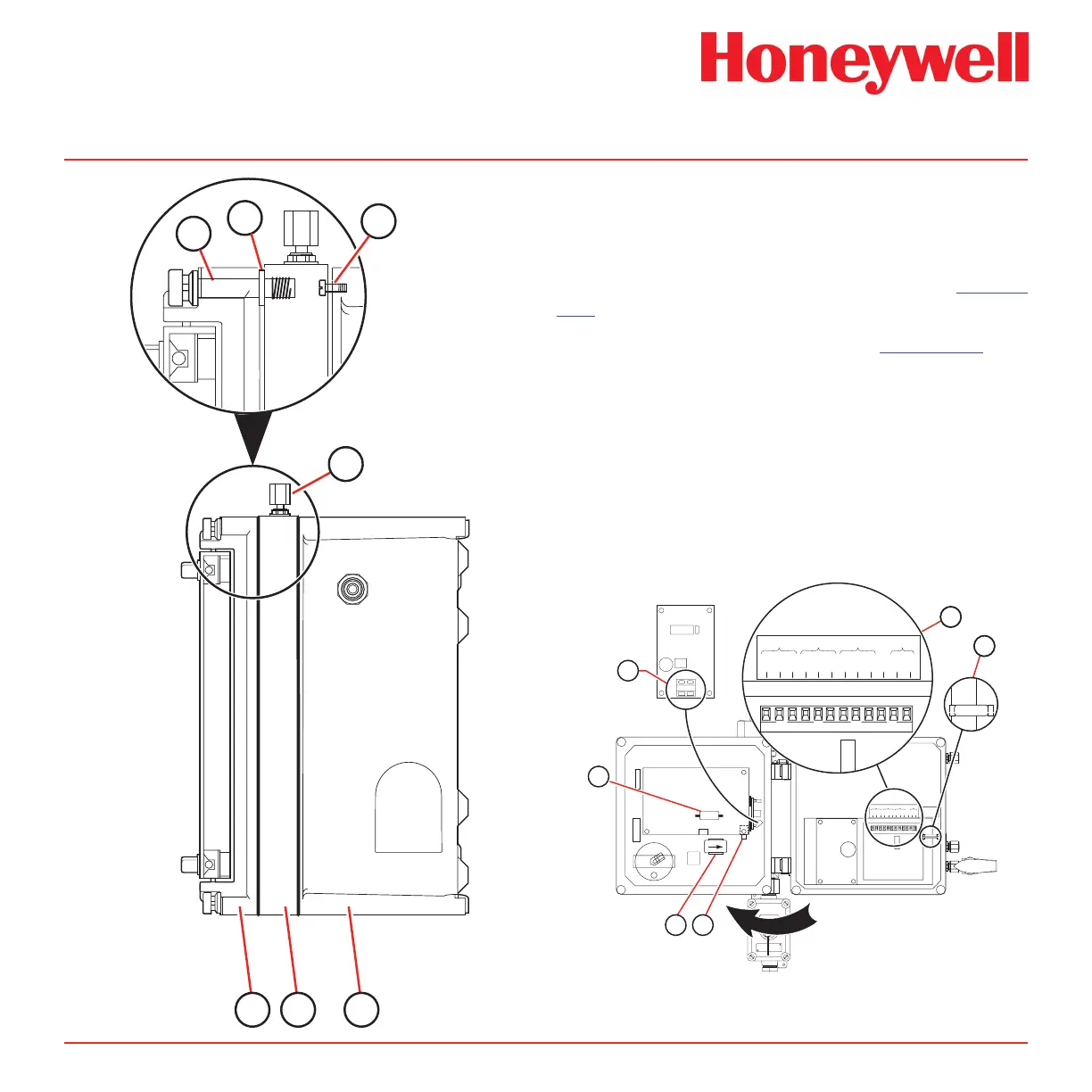
5.2.6 Output Connections
The illustration below shows the interior connection
points for the following terminations:
Remote reset option (60), if equipped. See Section
5.10.
RS-422 option (62), if equipped. See Section 5.5.
Terminal strip (61) for gas alarms relays, instrument fault
relay, and 4-20 mA output.
All wiring entering and exiting the SPM enclosure must
be properly seal fitted, dammed, and potted before
the instrument is put into service. After making the
connections, be sure that all wiring harnesses and
tubing lines are secure and will not be pinched when
the door is closed.
OFF ON
1 2 3 4 5 6 7 8 9 10 11 12
NC C NO NC C NO NC C NO + –
INSTRUMENT
RELAY
ALARM #1 ALARM #2 4 – 20
RS-422 OUTPUT
SEE MANUAL FOR
INSTALLATION
INSTRUCTIONS
1 2
870806
61
1 2 3 4 5 6 7 8 9 10 11 12
NC C NO NC C NO NC C NO + –
INSTRUMENT
RELAY
ALARM #1 ALARM #2 4 – 20
62
60
6665
67
 Loading...