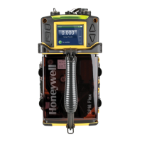
SPM Single Point Monitor
SPM Technical Handbook
TOC-2
2.3.5 Exhaust Line ................................................................................................... 2-4
2.3.6 High Pressure Locations ................................................................................. 2-4
2.4 SPM Output Connections ...................................................................................... 2-4
2.4.1 Output Pin Designations ................................................................................. 2-4
2.5 How to Open Instrument Cover ............................................................................ 2-5
3 Maintenance
3.1 Routine Maintenance Schedule ............................................................................ 3-2
3.2 Chemcassette
®
Replacement ................................................................................ 3-2
3.3 Verify System Response ....................................................................................... 3-2
3.4 Replacing Internal Filters ...................................................................................... 3-2
3.5 Replacing the Fuse ................................................................................................ 3-3
3.6 Caring for Chemcassettes
®
................................................................................... 3-3
3.7 Removing a Used Chemcassette
®
........................................................................ 3-4
3.8 Troubleshooting Guide .......................................................................................... 3-4
4 Specifications
4.1 General Instrument Specifications ....................................................................... 4-2
4.2 4-20 mA Output Signal .......................................................................................... 4-2
4.3 Verifying the 4-20 mA Output Signal .................................................................... 4-2
4.4 Output Signals ....................................................................................................... 4-3
4.5 Status Indicators .................................................................................................... 4-6
4.6 Display Messages .................................................................................................. 4-6
4.7 Fault Codes ............................................................................................................ 4-6
4.8 Output Terminal Status .......................................................................................... 4-7
4.9 Gas Response Specifications ............................................................................... 4-8
4.10 Sample Line Limitations .................................................................................... 4-11
4.11 Particulate Filters ............................................................................................... 4-11
5 Options
5.1 AccuPulse Dilution System .................................................................................. 5-2
5.1.1 AccuPulse Installation ..................................................................................... 5-2
5.2 Z-Purge System Option ......................................................................................... 5-2
5.2.1 Purge Installation ............................................................................................ 5-2
 Loading...
