WIRING
Using the DIP Switches
The wiring features are congured by DIP settings, which are described under the steam humidier cover.
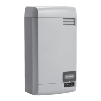
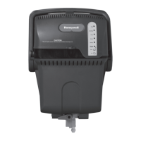
STEP ONE: Remove the Steam Humidier Cover
Loosen the cover screw.
Slide cover out from front.
With the cover removed, you will see six DIP switches
to the left of the user interface panel. This manual
refers to DIPs 1–6 from left to right.
STEP TWO: Understand the DIP Switches
DIPS 1 and 2 are used for maintenance.
DIP 1 and DIP 2: Together, these two DIPs specify
how often the automatic ush cycle is performed. See
“Routine Maintainence” on page 44.
2
3
4
5
6
MCR29608
65432
On
Off
1
Before Wiring Steam Humidier
Before wiring the steam humidier:
I will read the section “Understand the DIP Switches” beginning on this page
I will read the section “Deciding on the Wiring Conguration” beginning on page 29
CAUTION: Voltage Hazard.
Be sure steam humidier is not plugged in when removing the cover.
Steam Humidier System 69-2285—09 27
1
2
3
 Loading...