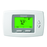
OPERATION TB6575/TB8575 SUITEPRO™ DIGITAL FAN COIL THERMOSTATS
13 62-0278—01
Energy Saving Modes
ACTIVITY SENSING
If Activity Sensing is enabled, any time the thermostat is not
touched (no single key is pressed) for the duration selected, the
thermostat automatically falls back into the Unoccupied
setpoints. When any key is pressed, the thermostat controls to
Occupied mode.
AUTO FAN RESET
If Auto Fan Reset is enabled (IS code #24, value 1 or 2), and a
constant fan speed is selected, the thermostat resets the fan to
Auto.
• Value = 1: The fan resets back to Auto after 2 hours.
• Value = 2: The fan resets back to Auto after 4 hours.
The start time is calculated after the initial call for Heat/Cool is
satisfied. Then, the two or four hour timing begins. The fan is set
back to Auto when the 2-hour or 4-hour delay expires.
REMOTE SETBACK
A
Remote Setback is activated by a dry contact closure on the
remote setback input from an occupancy sensor, time switch, or
hotel card key. The thermostat controls to the user/installer
defined setback setpoints for increased energy savings. The LCD
displays eCOnOmy SetbaCK just to the right of the main
temperature display to indicate the Remote Setback mode is
active.
For Heat Mode, when Remote Setback is enabled, the set point
changes to the remote setback heating setpoint.
For Cool Mode, when Remote Setback is enabled, the set point
changes to the remote setback cooling setpoint.
For 4 pipe applications with Auto Changeover, when Remote
Setback is enabled, the cool setpoint changes to the remote
setback cooling setpoint and the heat setpoint changes to the
remote setback heating setpoint. The new effective deadband is
the difference between the remote setback heating setpoint and
the remote setback cooling setpoint.
Fig. 27 illustrates the relationship between setpoints, Remote
Setback, and deadband for auto changeover.
Fig. 27. Auto Changeover deadband illustration.
VERSASPEED™ FAN RAMPING
Constant or Cycle mode —
This mode allows user to select the fan to run at either Auto or at
constant fan speeds (Low, Med, or Hi). Auto will cycle the fan
using the fan ramping algorithm. The appropriate fan speed is
selected according to Fig. 28.
Cycle mode —
In this mode, the fan is set to Auto. Auto will cycle the fan using
the fan ramping algorithm. The appropriate fan speed is selected
according to Fig. 28.
The fan ramping algorithm is illustrated in Fig. 28
Fig. 28. VersaSpeed™ fan ramping algorithm illustration.
Application Modes
This section describes the operation of each of the application
modes for the SuitePRO™ fan coil thermostats.
2 PIPES (HEAT OR COOL) WITH SEASONAL CHANGEOVER
This application supports the pipe sensor as a N.O., N.C., or
Analog input.
For the pipe analog sensor, see Fig. 29 and note that:
• When the pipe temperature is more than the pipe sensor
Threshold for Heating value (IS code #7), the system
changes to Heat mode.
• When pipe temperature is less than the pipe sensor
Threshold for Cooling value (IS code #6), the system changes
to Cool mode.
• When the pipe temperature is between the two threshold
values, the system mode remains unchanged.
Fig. 29. Heat/Cool Auto Changeover for pipe analog sensor.
2 PIPES (HEAT OR COOL) WITH MANUAL CHANGEOVER
In 2 pipe Manual Changeover, the thermostat system setting
must manually be changed to Heat or Cool.
2 PIPES (HEAT OR COOL) WITH AUXILIARY HEAT
This application supports the pipe sensor as a N.O., N.C., or
Analog input.
In Heat mode —
• If the water in pipe is hot, hot water is the heat source.
• If the water in pipe is cool, the auxiliary heat is the heat
source.
In Cool mode —
• If the water in pipe is hot, the thermostat has no control.
• If the water in pipe is cool, the cool water is the cool source.
If the thermostat is configured for Auxiliary Heat, a pipe purge
occurs once every 24 hours (see “Pipe Purge” on page 13).
4 PIPES (HEAT AND COOL) AUTO CHANGEOVER
In 4 pipe auto changeover, the system key is used to switch
between the heating setpoint and cooling setpoints. Use the Up
and Down arrow buttons to change the setpoint.
For this application, the setpoint settings and deadband are
illustrated in Fig. 30. The deadband is changed via IS code #10.
Fig. 30. 4 Pipe Auto Changeover setpoints and deadband.
Pipe Purge
Pipe purging is only active in 2 pipe fan coil modes and when a
pipe sensor is configured (IS code #2; value 3 or 6).
a
When Remote Setback is active, all buttons on the thermostat
are disabled. However, the button combinations to access
Installer Setup (IS) and Installer Test (IT) remain enabled.
UNOCCUPIED DEADBAND
DEADBAND
REMOTE SETBACK COOL SETPOINT
UNOCCUPIED DEADBAND
COOL SETPOINT
HEAT SETPOINT
REMOTE SETBACK HEAT SETPOINT
M27562
-2°F
+2°F
+4°F
-4°F
FAN SPEED IS HIGH
DIFFERENCE
BETWEEN
RT AND
SETPOINT
COOL
HEAT
SETPOINT
M27563
FAN SPEED IS MEDIUM
FAN SPEED IS LOW
FAN SPEED IS HIGH
FAN SPEED IS LOW
FAN SPEED IS MEDIUM
COOL THRESHOLD
(IS CODE 6)
HEAT MODE
M27564
COOL MODE
HEAT THRESHOLD
(IS CODE 7)
DEADBAND
COOLING SETPOINT
HEATING SETPOINT
M27565
 Loading...