TB7300 SERIES COMMUNICATING FAN COIL THERMOSTATS
17 62-2018—05
%RH disp Local %RH Display
Default value = OFF
Models with Humidity sensor
only
TB735xX5x14(x) models only
Enables the display of humidity below the room temperature on the
display
ON = Display %RH
OFF = No display of %RH
Lockout Keypad lockout levels
Default value = 0 No lock
See Table 12 for Lockout level details
Pipe No System type installation
Number of pipes
Default value = 4.0 Pipes
Defines the type of system installed
2.0 Pipes, will limit the number of sequences of operation available
from 0 to 3. Will enable heat/cool operation from the same output
(refer to wiring diagram)
4.0 Pipes, can access all the sequences of operation from 0 to 5. Will
enable heat/cool operation from different output (refer to wiring
diagram)
SeqOpera Sequence of operation
Default value = Sequence #1
Fan Menu Mode button menu
configuration
Default value = Menu #4
Menu presented is dependent on model used and sequence of
operation selected
Auto Mode operation for sequences 2 and 3 is dependent on Auto
Fan parameter
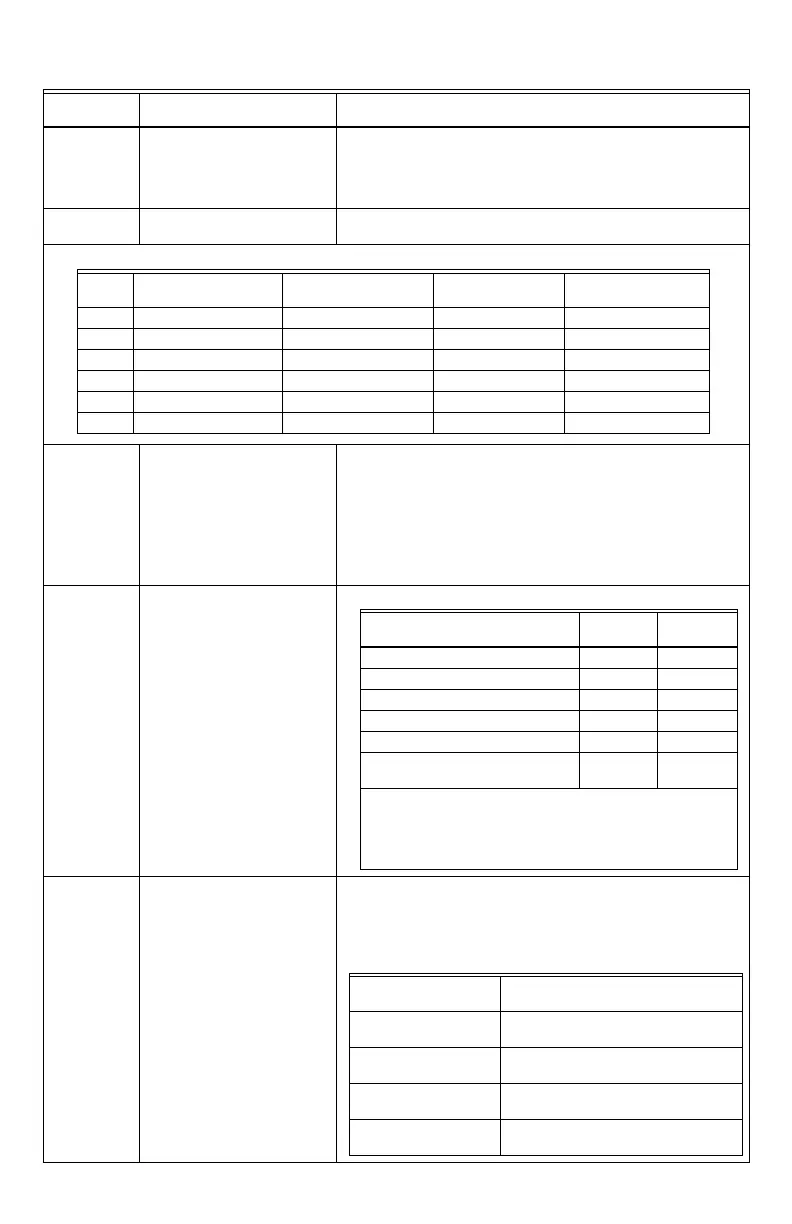
Table 11. Configuration parameters
Configuration
parameters Default value Significance and adjustments
Table 12. Keypad Lockout Levels
Level
Occupied temperature
setpoints System mode setting Fan mode setting Unoccupied Override
0 Yes access Yes access Yes access Yes access
1 Yes access Yes access Yes access No access
2 Yes access No access No access Yes access
3 Yes access No access No access No access
4 No access No access No access Yes access
5 No access No access No access No access
Default value = Sequence #1
System =
2 Pipes
System =
4 Pipes
0 = Cooling Only Yes access Yes access
1 = Heating only Yes access Yes access
2 = Cooling With Reheat Yes access Yes access
3 = Heating With Reheat Yes access Yes access
4 = Cooling/Heating 4 pipes No access Yes access
5 = Cooling/Heating 4 pipes with
Reheat
No access Yes access
For single output applications, the system access is also
limited if UI3 is configured for local changeover COS, COC/NC
or COC/NC. The current water temperature detected by the
UI3 then limits the system mode available for the local
configuration or network write.
0 = Low-Med-High 3 Speed configuration using 3 fan
relays (L-M-H)
1 = Low-High 2 Speed configuration using 2 fan
relays (L-H)
2 = Low-Med-High-Auto 3 Speed configuration with Auto fan
speed mode using 3 fan relays (L-M-H)
3 = Low-High-Auto 2 Speed configuration with Auto fan
speed mode using 2 fan relays (L-H)
4 = On-Auto Single Speed configuration. Auto is for
Fan on demand/On is On all the time