TB7300 SERIES COMMUNICATING FAN COIL THERMOSTATS
62-2018—05 8
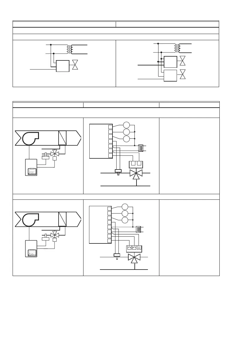
Typical applications
Analog control
TB7300F5x14(x), TB7305F5x14(x), TB7350F5x14(x) and TB7355F5x14(x)
Schematic Wiring Settings
2 pipe system cooling and/or heating: TB7300A5x14(x), TB7300C5x14(x) and TB7305C5x14(x) on/off N.C.
actuator
Normally closed on/off valve
cooling and/or heating
Mandatory
•Pipe no = 2 pipes
•CntrltTyp = On/Off
•Fan Menu = 0 (L-M-H)
•FL time = as per actuator
If cooling only set:
• SeqOpera = 0 Cooling only
If heating only set:
• SeqOpera = 1 Heating only
If heat/cool auto-changeover
with a local water temperature
sensor set:
• SeqOpera = 0 Cooling only
•UI3 = COS
2 pipe system cooling and/or heating: TB7300C5x14(x) and TB7305C5x14(x) floating actuator
Modulating floating valve
cooling and/or heating
Mandatory
•Pipe no = 2 pipes
•CntrltTyp = Floating
•Fan Menu = 0 (L-M-H)
•FL time = as per actuator
If cooling only set:
• SeqOpera = 0 Cooling only
If heating only set:
• SeqOpera = 1 Heating only
If heat/cool auto-changeover
with a local water temperature
sensor set:
• SeqOpera = 0 Cooling only
•UI3 = COS
2 Pipe applications 4 Pipe applications
24 V~ HOT
24 V ~ COM
HEATING/COOLING VALVE
AO 1
COM
24 VAC
0-10 VDC
M16926
24 V~ HOT
24 V ~ COM
HEATING VALVE
COOLING VALVE
AO 2
AO 1
COM
24 VAC
0-10 VDC
COM
24 VAC
0-10 VDC
M16919
ROOM TEMPERATURE
CONTROL THERMOSTAT
3 SPEED FAN
M16950
24 VAC FAN RELAYS
HIGH
MED
LOW
FAN-H
FAN-M
FAN-L
UI 3 COS
24 V~ COM
24 V ~ HOT
BO 2 N.C.
OPTIONAL SUPPLY WATER
TEMPERATURE SENSOR
M16953
ROOM TEMPERATURE
CONTROL THERMOSTAT
3 SPEED FAN
M16950
24 VAC FAN RELAYS
HIGH
MED
LOW
FAN-H
FAN-M
FAN-L
UI 3 COS
24 V~ COM
24 V ~ HOT
BO 2 CLOSE
BO 1 OPEN
OPTIONAL SUPPLY WATER
TEMPERATURE SENSOR
M16954