51-52-25-130
September 2005
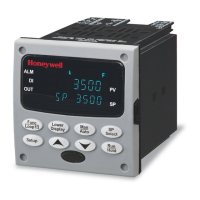
Quick Start Guide for UDC3500 Universal Di
ital Controller
For detailed instructions see UDC3500 Controller Product Manual 51-52-25-120.
Step 1. Model Number Interpretation
Write your controller model number in the boxes. Then refer to Tables I, II, III, IV, and V . Circle the corresponding options to identify your controller’s features. A dot indicates the feature is available.
- - - - -
Key Number
Table I
Table II
Table III
Table IV
Table V
KEY NUMBER - UDC3500 Single & Dual Loop Controller
Selection
Digital Controller for use with 90 to 264Vac Power + Current Output #1 DC3500
Digital Controller for use with 24Vac/dc Power + Current Output #1 DC3501
TABLE I - Specify optional Output and/or Alarms
None
TABLE II - Communications and Software Selections
0 _ _ _
1 _ _ _
2 _ _ _
3 _ _ _
_ 0 _ _
_ A _ _
_ B _ _
_ C _ _
_ D _ _
_ E _ _
_ F _ _
_ G _ _
_ _ 0 _
_ _2 _
_ _ _ 0
_ _ _ C
Real-Time Clock
_ E
None
Three (3) E-M Relay (5 Amp Form C)
Electro Mechanical Relay (5 Amp Form C)
A _
_ 0
T _
R _
Description
Current Output (4 to 20mA, 0 to 20 mA) (Current Output #3)
C _
E _
0 _
Output #2
Solid State 1 Amp (Zero-Crossing Type)
Availability
Math + HealthWatch
Math Option
Set Point Programming (1 Program, 20 Segments)
Set Point Programming Plus Math
HealthWatch
Open Collector transistor output
Dual 2 Amp Relays (Form A) (Heat/Cool, Pos Prop, TPSC, Relays 1 & 2)
Relay Outputs #3, #4
and #5
Software Selections
None
Current Output #2 + (4) Digital Inputs
Current Output #2 + (4) Digital Inputs + Modbus RS-485
10 Base-T Ethernet (Modbus RTU) + (4) Digital Inputs
SPP + Math + HealthWatch
SPP + HealthWatch
Standard Functions, Includes Accutune
Communications
Loops of Control
2 Loops + Internal Cascade
Single Loop
None
Real-Time Clock (RTC)
TABLE III - Input types can be changed in the field
Selection
1 _ _
2 _ _
3 _ _
1 5 _
Carbon, Oxygen or Dewpoint (Requires Input 2)
1 6 _
_ 0 _
_ 1 _
_ 2 _
Two HLAI instead of 1 LLAI
_ 3 _
_ _0
_ _1
_ _2
Two HLAI instead of 1 LLAI _ _3
Slidewire Input for Position Prop. (Requires Dual Relay Output)
_ _4 aa
Input 2
None
None
TC, RTD, mV, 0-5V, 1-5V, 0-20mA, 4-20mA
TC, RTD, mV, 0-5V, 1-5V, 0-20mA, 4-20mA, -1-1V, 0-10V
Input 3
Relative Humidity (Requires Input 2)
TC, RTD, mV, 0-5V, 1-5V, 0-20mA, 4-20mA, -1-1V, 0-10V
Input 1
TC, RTD, mV, 0-5V, 1-5V
TC, RTD, mV, 0-5V, 1-5V, 0-20mA, 4-20mA
TC, RTD, mV, 0-5V, 1-5V, 0-20mA, 4-20mA
TC, RTD, mV, 0-5V, 1-5V, 0-20mA, 4-20mA, -1-1V, 0-10V
TABLE IV - Options
0 _ _ _ _
1 _ _ _ _
_ 0 _ _ _
_ T _ _ _
_ _ 0 _ _
_ _ _ 0 _
_ _ _ _ 0
TABLE V - Product Manuals
Product Information on CD - (English) 0 _
English Manual (Hard Copy) E _
French Manual (Hard Copy) F _
German Manual (Hard Copy) G _
Italian Manual (Hard Copy) I _
Spanish Manual (Hard Copy)
S _
_ 0
_ C
Approvals
CE (Standard)
CE, UL and CSA
Tags
None
Stainless Steel Customer ID Tag - 3 lines w/22 characters/line
Future Options
None
None
None
None
Certificate of Conformance (F3391)
Manuals
Certificate
Step 2. Dimensions and mounting
Max. panel thickness
19,1
0.75
Panel
Cutout
92,0 + 0,8
- 0,00
3.62 + 0.03
- 0.00
92,0 + 0,8
-
0,00
3.62 + 0.03
-
0.00
mm
inches
17,9
0.70
148,0
5.81
90,6
3.57
108,6
4.28
9,0
0.35
Step 3. Wiring
L1
L2/N
4
5
6
7
8
9
29
30
34
35
36
28
10
11
12
13
14
15
16
18
17
Ethernet
SHIELD 4
RXD - 24
RXD + 25
TXD - 26
TXD + 27
R
T
D
AC/DC
Line
Voltage
Earth Ground
Hot
Neutral
+
-
-
+
-
+
-
+
Input #1
Input #2
RS485
SHIELD 4
D+ (B) 26
D- (A) 27
L
i
ne
ar
m
A
T
her
m
oc
oupl
e
L
i
near
V
/
m
V
31
32
33
Same as Input #1
Digital Inputs #1 through #4
Output #2
m
A
D
C
+
+
-
-
O
p
e
n
C
o
l
l
e
c
t
o
r
S
o
l
i
d
S
t
a
t
e
R
e
l
a
y
S
i
n
g
l
e
R
e
l
a
y
D
u
a
l
R
e
l
a
y
2
1
19
20
21
22
23
24
25
27
26
Input #3
Same as Input #1
plus Slidewire input
C/J
+
-
Current Output #1
Current Output 2
+ 24
–25
Relays #3, #4 and #5
L1
L2/N
4
5
6
7
8
9
29
30
34
35
36
28
10
11
12
13
14
15
16
18
17
Ethernet
SHIELD 4
RXD - 24
RXD + 25
TXD - 26
TXD + 27
R
T
D
AC/DC
Line
Voltage
AC/DC
Line
Voltage
Earth Ground
Hot
Neutral
+
-
-
+
-
+
-
+
Input #1
Input #2
RS485
SHIELD 4
D+ (B) 26
D- (A) 27
L
i
ne
ar
m
A
T
her
m
oc
oupl
e
L
i
near
V
/
m
V
31
32
33
31
32
33
Same as Input #1
Digital Inputs #1 through #4
Output #2
m
A
D
C
+
+
-
-
O
p
e
n
C
o
l
l
e
c
t
o
r
S
o
l
i
d
S
t
a
t
e
R
e
l
a
y
S
i
n
g
l
e
R
e
l
a
y
D
u
a
l
R
e
l
a
y
2
1
19
20
21
22
23
24
25
27
26
Input #3
Same as Input #1
plus Slidewire input
C/J
+
-
Current Output #1
Current Output 2
+ 24
–25
Relays #3, #4 and #5
Open
Wipe
Close
Open
Wipe
Close
Open
Wipe
Close
Step 4. Configuration Procedure
Step Operation Press Result
1 Enter Set Up Mode
SetupSetup
Upper Display = SETUP
Lower Display = TUNING (This is the first Set Up Group title)
2 Select any Set Up
Group
SetupSetup
Sequentially displays the other Set Up group titles shown in the prompt hierarchy. See User Manual.
You can also use the
or keys to scan the Set Up groups in both directions. Stop at the Set Up group title that describes the
group of parameters you want to configure. Then proceed to the next step.
3 Select a Function
Parameter
Func
Loo
1/2
Upper Display = the current value or selection for the first function prompt of the selected Set Up group.
Lower Display = the first Function prompt within that Set Up group.
Sequentially displays the other function prompts of the Set Up group you have selected. Stop at the function prompt that you want to change,
then proceed to the next step.
4 Change the Value
or Selection
or
Increments or decrements the value or selection that appears for the selected function prompt. If you change the value or selection of a
parameter while in Set Up mode but then decide not to enter it, press the MAN/AUTO key once. This will recall the original configuration.
This “recall” procedure does not work for a Field Calibration process. Field Calibration is a one-way operation.
5 Enter the Value or
Selection
Func
Loo
1/2
Enters value or selection made into memory after another key is pressed.
6 Exit Configuration
Lower
Display
Lower
Display
Lower
Display
Exits configuration mode and returns controller to the same state it was in immediately preceding entry into the Set Up mode. It stores any
changes you have made.
If you do not press any keys for 30 seconds, the controller times out and reverts to the mode and associated display used prior to entry into
Set Up mode.
Page 1 of 6