UNIPOINT OPERATING MANUAL 2306M5001 MAN0638 ISSUE 7 01/2011
9
4.3 Maximum Cable Lengths
4.3.1 mA Detectors
To calculate the maximum cable run length from power source to the detector refer to the
following example diagram and formula.
Rloop = (Vcontroller - 1.5V - Vdetector min) / Idetector
Maximum cable run length = Rloop / cable per metre resistance where:
Rloop = maximum working cable loop resistance
Vcontroller = maximum available supply voltage at controller
Vdetector min = minimum voltage at which the connected sensor can operate
(sensor dependent, see individual sensor technical manual/
data sheets)
Idetector = sensor maximum drawn current. 30mA for 2 wire mA detectors.
See individual detector technical manual/data sheets for max power
consumption of 3 wire detectors.
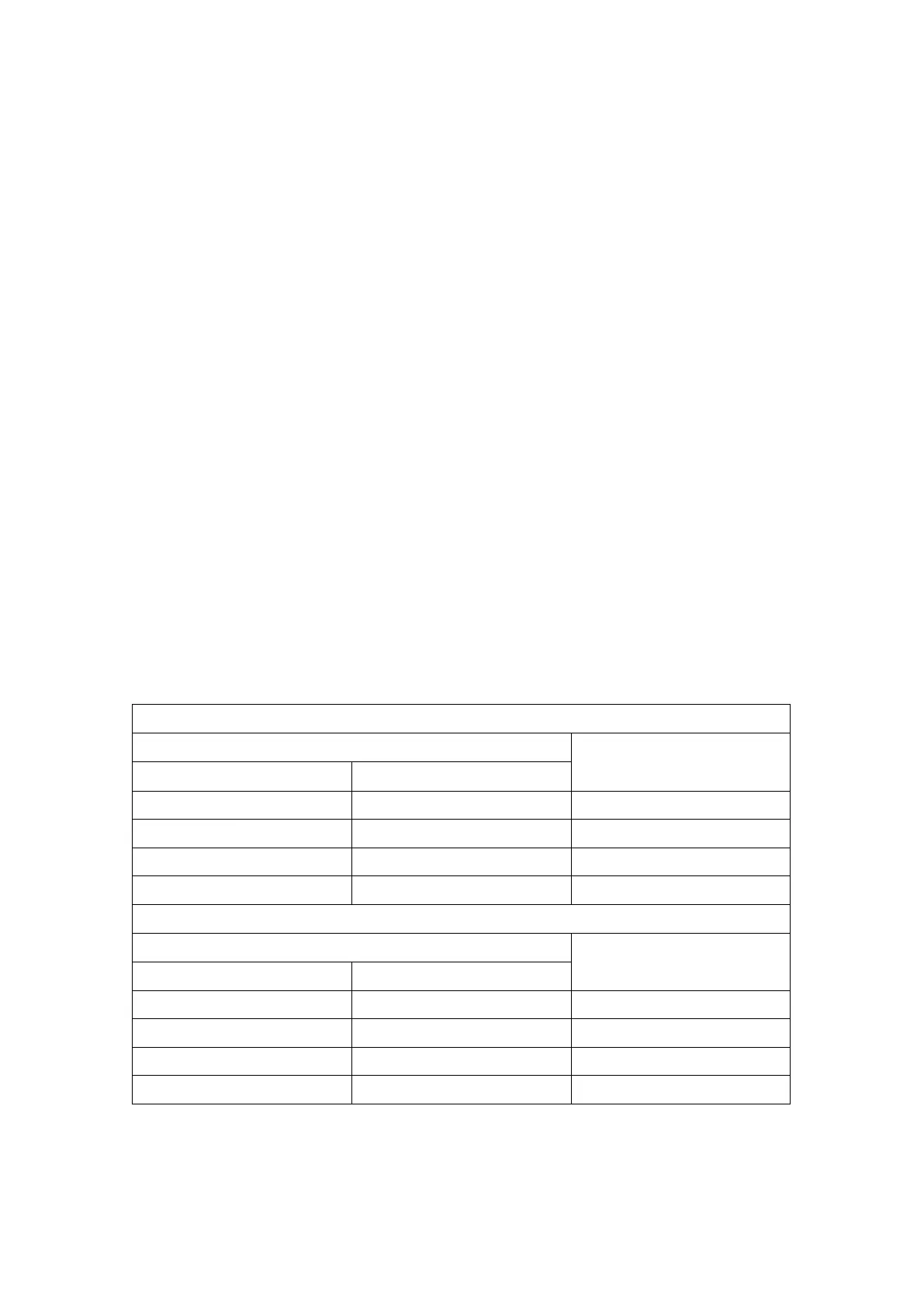
4.3.2 mV Detectors
To calculate the maximum cable run length to the detector refer to the following typical
example cable resistances. Max cable loop resistance = 28 ohms.
Solid Copper Conductor
Cross Sectional Area Maximum resistance at 20ºC
(mm
2
) AWG (ohm/bucle/km)
0.50 21 72
0.75 19 50
1.00 18 36
1.50 16 24
Stranded Copper Conductor
Cross Sectional Area Maximum resistance at 20ºC
(mm
2
)
AWG
(ohm/bucle/km)
0.50 21 73.6
0.75 19 49
1.00 18 35.2
1.50 16 23.4
 Loading...