XNX Universal Transmitter
Installation and Operation
59
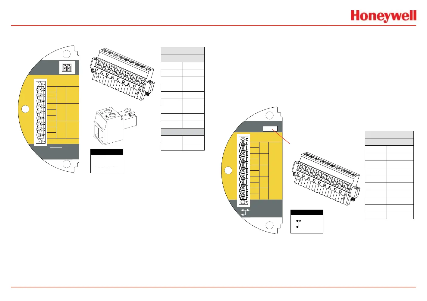
normally energized indicating proper operation. In the event of
power failure or fault, the C-NO connection will open.
Warning: Power
externally supplied.
Disconnect at source
prior to servicing.
3-5
3-4
3-3
3-2
3-1
3-6
3-7
3-8
3-9
C
NC
TB4
Remote
Reset SW
Relay Ratings
250VAC 5A
24VDC 5A
NO
C
NC
NO
NC
C
NO
Fault Level 2 Level 1
TB-3 RELAY
TB3 Relay Connections
Warning: Power externally
supplied, disconnect at source
prior to servicing
Relay Contact Ratings:
250 VAC 5 amps
24 VDC 5 amps
Relay
TB3
1 NC
2 C
3 NO
4 NC
5 C
6 NO
7 NC
8 C
9 NO
TB4
1 1
2 2
1
2
3
4
5
6
7
8
9
TB3
1
2
TB4
Figure 57. XNX relay option board terminal blocks
Modbus
The optional Modbus interface allows all transmitter local user
interface functions and parameter settings to be transmitted.
Modbus is a master-slave protocol. Only one master (at a time) is
connected to the bus. Modbus communication is always initiated
by the master. The slave nodes never transmit data without
receiving a request from the master node. The slave nodes never
communicate with each other. The master node initiates only one
Modbus transaction at a time.
Terminals 3-1 through 3-4 are provided to facilitate
bus wiring; there is no internal connection to other XNX
circuitry. Terminal 3-1 is connected internally to 3-2.
Similarly, terminal 3-3 is connected to 3-4
3-5
3-4
3-3
3-2
3-1
3-6
3-7
3-8
3-9
3-10
A
-
-
+
+
A
B
B
S
TB-3 Modbus
S
Use shorting jumper
supplied to maintain
connection during
service
S5 EOL Term
Out
In
R
T
=120
TB3 Modbus Connections
Use Jumper
to maintain
connection
during service
SW5 - Loop Termination
Modbus
TB3
1 +
2 +
3 -
4 -
5 A
6 A
7 B
8 B
9 S
10 S
1
2
3
4
5
6
7
8
9
10
Figure 58. Modbus option board terminal block/jumper switch
 Loading...

