XNX Universal Transmitter Quick Start Guide
36
5 Options
5.1 Local HART
®
Interface
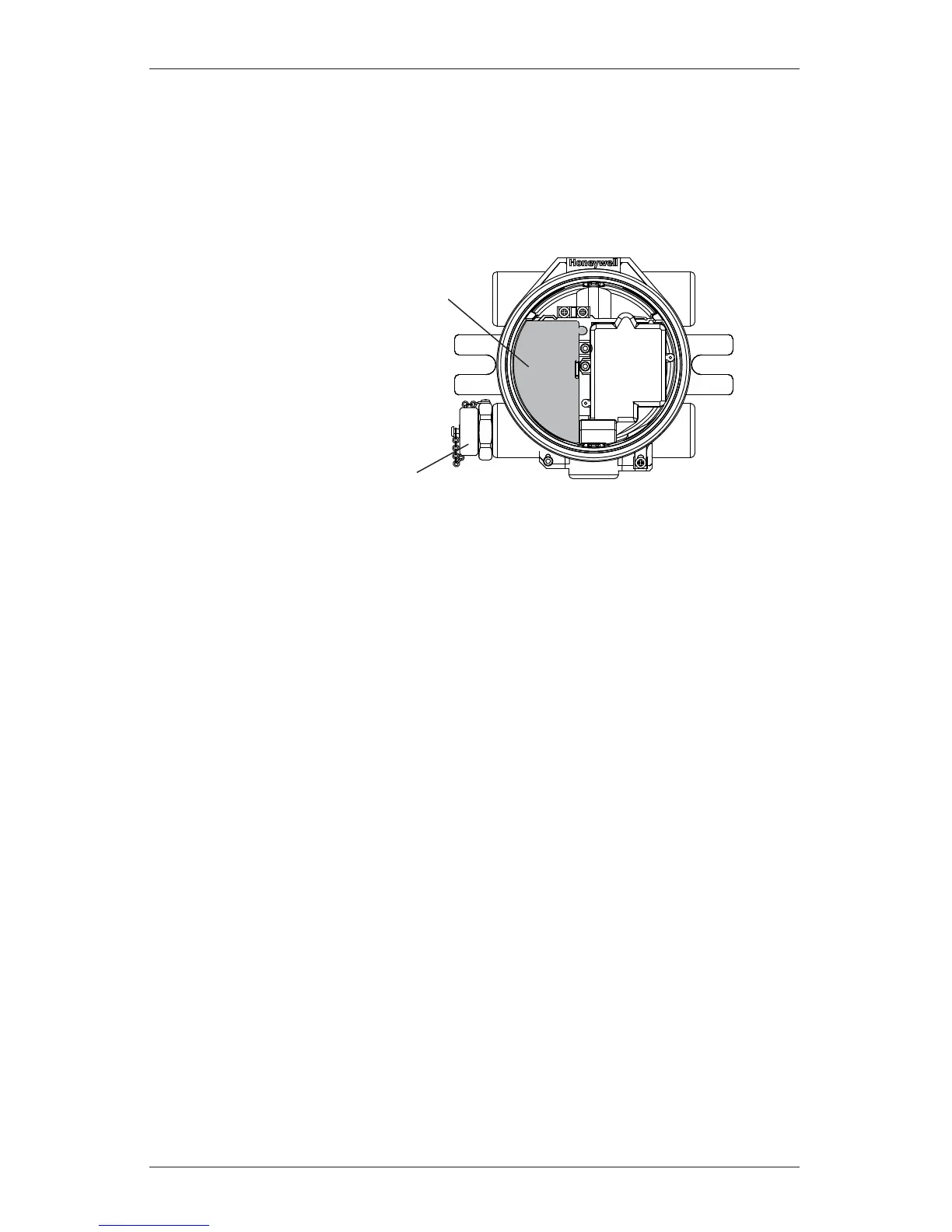
Available with any sensor technology or option, this option provides an external
access to the HART
®
interface in the XNX. An IS barrier inside the XNX allows
the user to attach an external hand-held interrogator for programming and
configuration. The external interface is installed in the lower left cable/conduit
entry of the XNX and is intrinsically safe (IS).
Intrinsically Safe Barrier
for HART Interface
HART Handheld Interface
Connector w/Protective Cap
Figure 23. XNX Universal Transmitter with HART
®
interface IS barrier installed
5.2 Relays
The relay option (XNX-Relay) provides 3 form “C” (SPDT) normally/ open/
normally closed (NO/NC) contacts for alarm and fault indication. A remote reset
is provided to silence alarms. TB4 is provided as a connection to a user installed
momentary switch to silence alarms remotely.
Exploring the functionality of the relay option board’s remote reset switch
The remote reset switch (designated TB-4 and labeled “Remote Reset SW”) is
located on the relay option board. It provides a remote hardware-based reset of
faults and alarms to the transmitter. In the event that direct access to the Local
User (LUI) and HART
®
interfaces is not possible, alarms and faults from an XNX
transmitter may be reset remotely using a switch.
The transmitter can be reset by activating a switch (Off-Mom). This will
momentarily close the circuit between the two pins of TB4, providing the same
functionality as a Reset Alarms & Faults command performed from the main
screen of the LUI or the HART
®
interface.
NOTE:
Relays are not available when the Modbus
®
or Foundation Fieldbus options
are installed.
Wiring for the relays is through an available cable/conduit entry to a pluggable
terminal block. See Figure 24 for the terminal block legend.
NOTE:
A second, black-handled screwdriver is included for use on terminal blocks 2
and 4. This tool is smaller than the magnetic wand and is designed to t into
the terminal connections on TB4.
 Loading...


