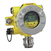
XNX Universal Transmitter Quick Start Guide
7
HAZARDOUS LOCATIONS INSTALLATION REQUIREMENTS UL/CSA/FM
• To reduce the risk of ignition of hazardous atmospheres, conduit runs must have a
pour gland installed within 18 inches (457mm) of enclosure.
• All ¾ inch NPT conduit, stopping plugs and adapters must be installed with 5 ¼
threads (minimum) engaged to Maintain Explosion Proof rating.
• The XNX Cover Assembly must be fully seated to enclosure 9 threads (minimum)
to maintain Explosion Proof rating.
• Stopping Plugs supplied (Honeywell Part Number 1226-0258) are approved for
use ONLY with the XNX Universal Transmitter.
• For units tted with the optional relay module: Relay contact ratings are 250 VAC
5A, 24 VDC 5A Resistive Loads Only.
• Use copper conductors only, 60/75°C. Terminal block screws should be tightened
to 4.5 lb/in maximum.
• For models XNX-UT**-*****, refer to XNX control drawing 1226E0402 or, for
models
• XNX-BT**-*****, refer to control drawing 1226E0454 for additional information
regarding IS function (local HART and EC personalities).
• XNX Universal Transmitters carrying UL/CSA/FM approvals that are congured
for devices measuring %LEL will not allow adjustments to the full scale value. The
range is xed at 100%.
HAZARDOUS LOCATIONS INSTALLATION REQUIREMENTS ATEX
• Read and understand Technical Manual 1998M0738 before installation and use.
• Use only Certied M25 cable glands for installation.
• Shielded armoured cable is required for CE compliance.
• Special conditions for safe use
• The following applies to the HART Barrier intrinsically safe circuits: For
installations in which both the Ci and Li of the intrinsically safe apparatus
exceeds 1% of the Co and Lo parameters of the associated apparatus
(excluding the cable), then 50% of Co and Lo parameters are applicable and
shall not be exceeded, i.e. the Ci of the device plus the C of the cable must be
less than or equal to 50% of the Co of the associated apparatus, and the Li of
the device plus the L of the cable must be less than or equal to 50% of the Lo
of the associated apparatus.
• For circuits connected to the EC barrier in which the capacitance and
inductance exceed 1% of the permitted values, then the maximum permitted
capacitance is limited to 600nF for group IIC and 1uF for group IIIC.
• The connection to the HART circuit shall be rated a minimum of IP 6X.
 Loading...


