EN
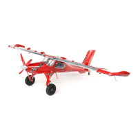
Commander mPd 1.4m
14
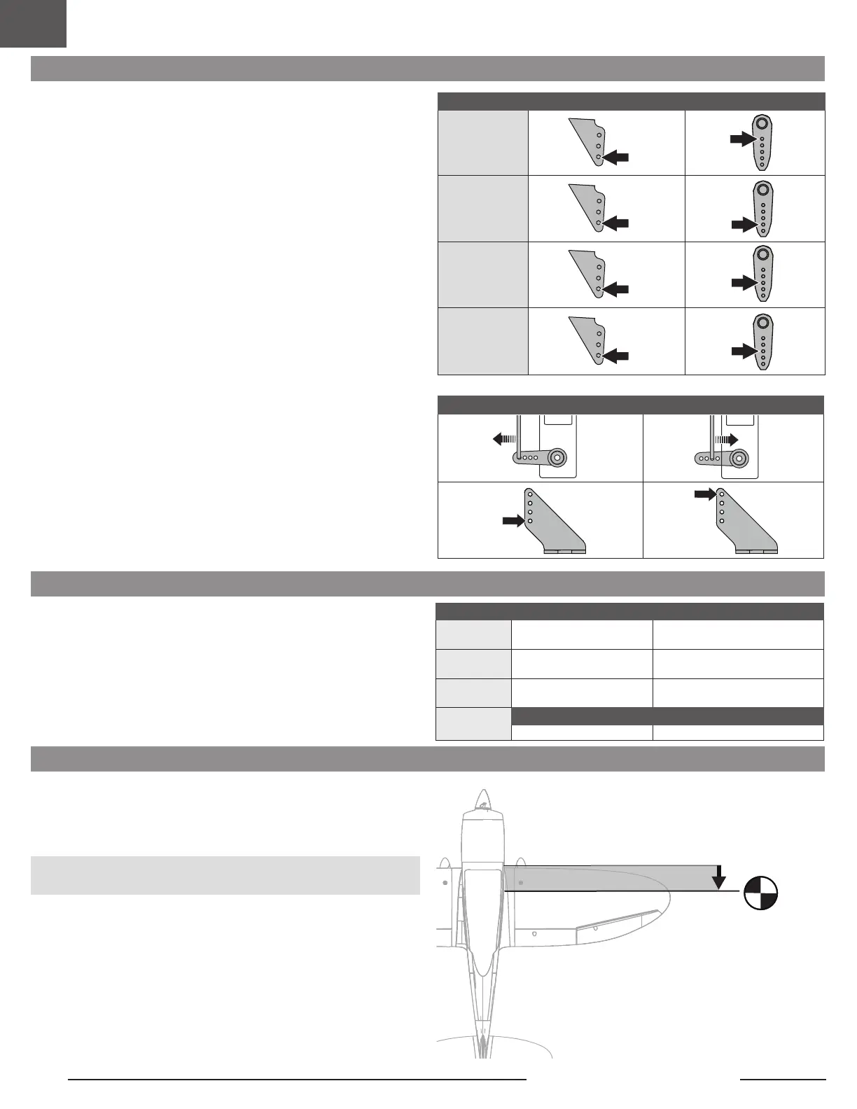
The table to the right shows the factory settings for the control horns and servo
arms. Fly the aircraft at factory settings before making changes.
Control Horn and Servo Arm Factory Settings
Control Horns Servo Arms
Elevator
Rudder
Ailerons
Flaps
More control throw Less control throw
High Rate Low Rate
Aileron
p = 25mm
q = 25mm
p = 18mm
q = 18mm
Elevator
p = 20mm
q = 20mm
p = 15mm
q = 15mm
Rudder
= 50mm
= 50mm
= 40mm
= 40mm
Flaps
Partial Full
q = 20mm q = 40mm
Dual Rates and Control Throws
Program your transmitter to set the rates and control throws to the values given.
These values have been tested and are a good starting point to achieve
successful flight.
After flying, you may choose to adjust the values for the desired control response.
Center of Gravity (CG)
The CG location is measured from the leading edge of the wing at the root. This CG
location has been determined with the recommended 4S 2200mAh LiPo Battery
(SPMX22004S30).
Tip: Measure the CG with the aircraft inverted.
CAUTION: Install but do not connect the battery while checking the CG. Personal
injury may result.
back from leading
edge of wing at the
fuselage.
85mm +/- 3mm
 Loading...