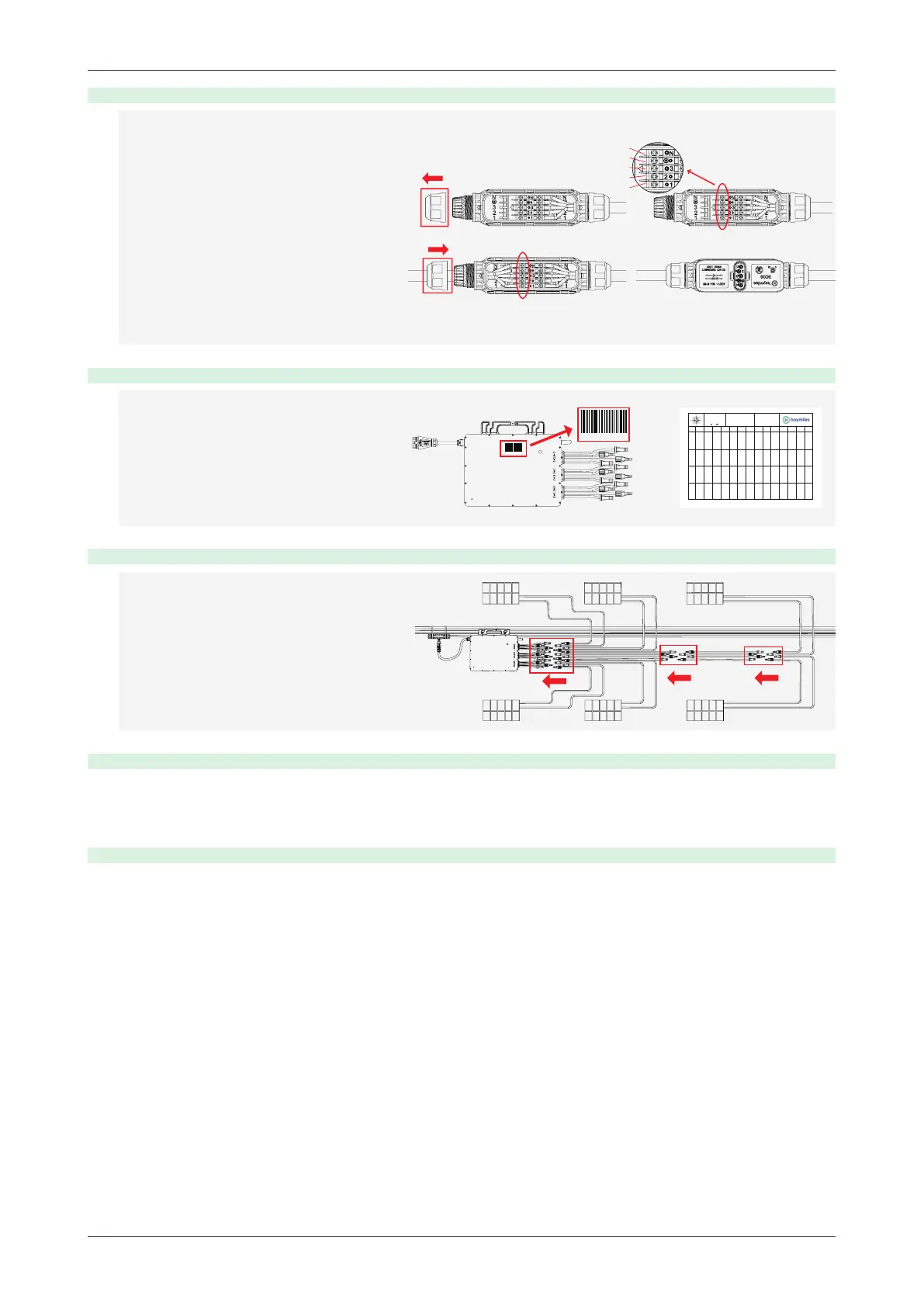
A ) Prepare the 3P-AC End Cable with the
proper length, insert one side of the cable
into the seal nut. Match the L1, L2, L3, N
and Ground line into the slot accordingly.
Tighten the screws, and then tighten the
cap back to the connector. Plug the upper
cover back to the 3P-AC bus connector.
B ) Connect the other side of the AC End Cable
to the distribution box, and wire it to the
local grid network.
Step 3. Install AC End Cable
A ) Peel the removable serial number label
from each microinverter (shown as
picture).
B ) Afx the serial number label to the
respective location on the installation map
Step 4. Create an Installation Map
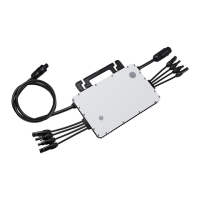
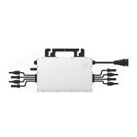
A ) Mount the PV modules above the
microinverter.
B ) Connect the PV modules’ DC cables to the
DC input side of the microinverter.
Step 5. Connect PV Modules
A ) Turn on the AC breaker for the branch circuit.
B ) Turn on the main AC breaker for the house. The system will start to generate power after several minutes.
Step 6. Energize the System
Refer to the DTU User Manual or DTU Quick Install Guide, and Quick Installation Guide for HMP Online Registration
to install the DTU and set up monitoring system.
Step 7. Monitoring System Set Up
© 2020 Hoymiles Power Electronics Inc. All rights reserved.
11
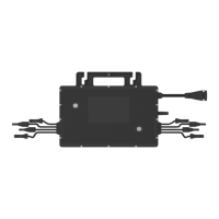
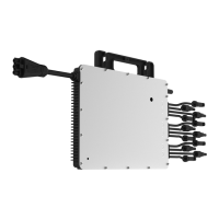
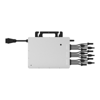
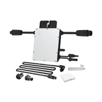
Three-phase Microinverter HMT-1800/2250 About Installation
N
PE
L3
L2
L1
o sheet ______
o sheet ______ AP040228 REV1.1
Panel Group:
Azimuth:
ilt:
Sheet_ of __
Customer Information DT Serial Number:
10 12 13 14
o sheet ________
o sheet ________
138264700571
138264700571

 Loading...