Table 6-1 Bottom covers, feet, and their descriptions and part numbers (continued)
Description Spare part number
● Snow white L22568-001
● Serenity mint L22570-001
● Pale gold L22572-001
● Scarlet red L22574-001
● Twilight blue L22576-001
● Maroon burgundy L22578-001
● Tranquil pink L25502-001
● Lumiere blue L47084-001
● Berry mauve L47086-001
1. Prepare the computer for disassembly (Preparation for disassembly on page 32).
2. Remove the optical drive (see Optical drive on page 33).
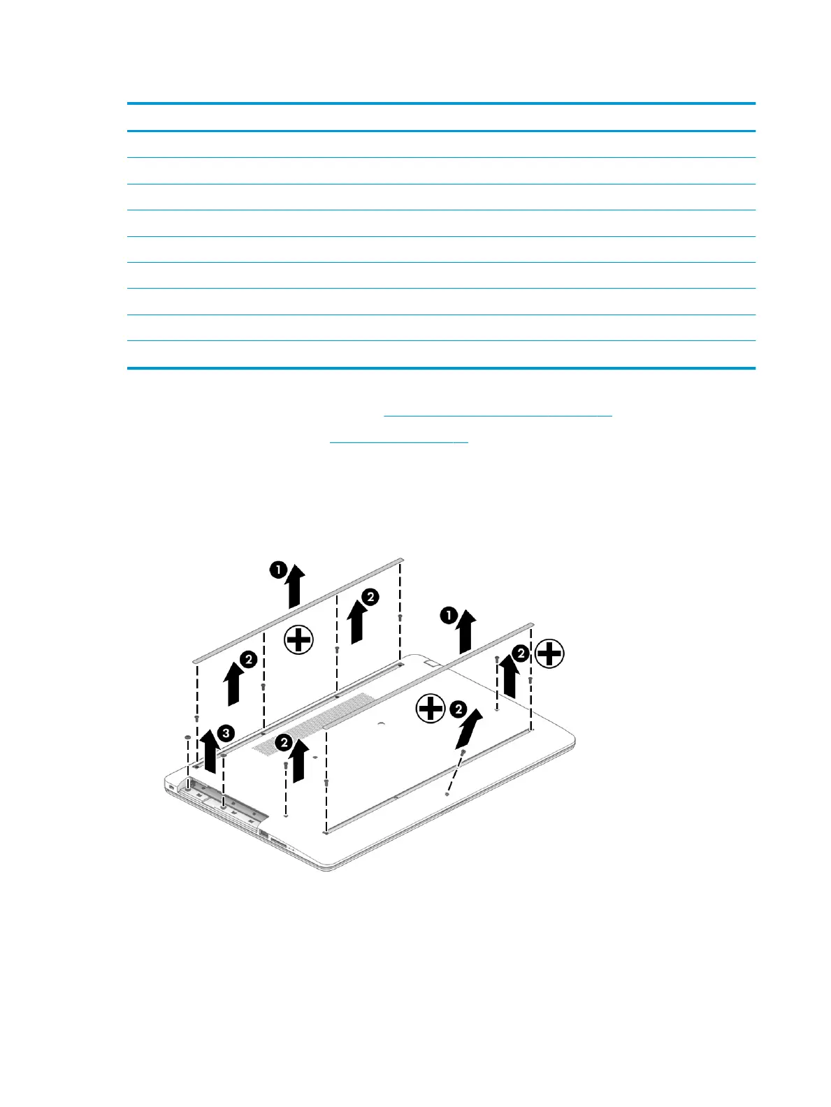
Remove the bottom cover:
1. Peel the rubber feet o the bottom of the computer (1).
2. Remove the nine Phillips M2.5 × 6.0 screws (2) and the two Phillips broad head M2.0 × 2.0 screws (3)
from the optical drive bay.
38 Chapter 6 Removal and replacement procedures for authorized service provider parts
 Loading...