274
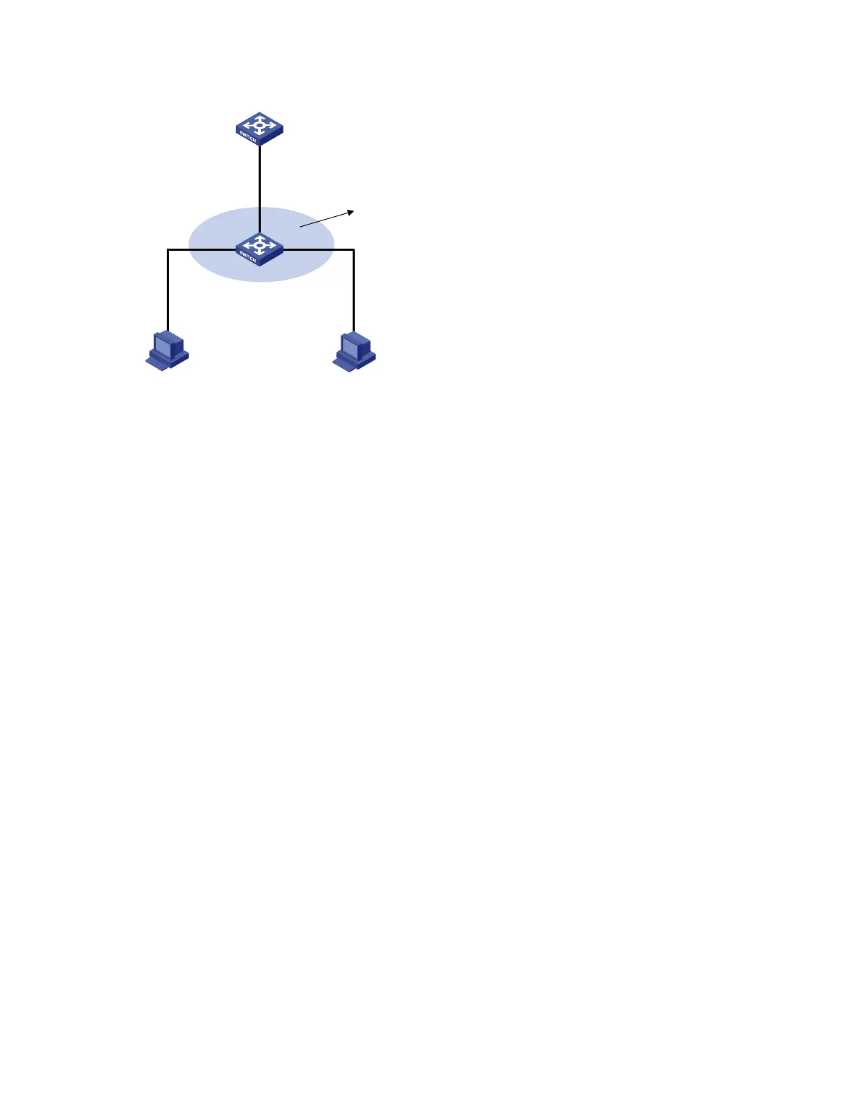
Figure 84 Network diagram for ARP detection configuration
Switch A
Switch B
Host A Host B
Vlan-int10
10.1.1.1/24
DHCP server
GE1/0/2
GE1/0/1
GE1/0/3
DHCP client DHCP client
VLAN10
DHCP snooping
Configuration procedure
1. Add all the ports on Switch B to VLAN 10, and configure the IP address of VLAN-interface 10 on
Switch A. (details not shown)
2. Configure Switch A as a DHCP server
# Configure DHCP address pool 0.
<SwitchA> system-view
[SwitchA] dhcp enable
[SwitchA] dhcp server ip-pool 0
[SwitchA-dhcp-pool-0] network 10.1.1.0 mask 255.255.255.0
3. Configure Host A as DHCP client, and Host B as user respectively. (details not shown)
4. Configure Switch B
# Enable DHCP snooping.
<SwitchB> system-view
[SwitchB] dhcp-snooping
[SwitchB] interface gigabitethernet 1/0/1
[SwitchB-GigabitEthernet1/0/1] dhcp-snooping trust
[SwitchB-GigabitEthernet1/0/1] quit
# Enable ARP detection for VLAN 10.
[SwitchB] vlan 10
[SwitchB-vlan10] arp detection enable
# Configure the upstream port as a trusted port and the downstream ports as untrusted ports (a port is an
untrusted port by default).
[SwitchB-vlan10] interface gigabitethernet 1/0/1
[SwitchB-Gigabitethernet1/0/1] arp detection trust
[SwitchB-Gigabitethernet1/0/1] quit
# Configure a static IP source guard binding entry on interface GigabitEthernet1/0/3.
[SwitchB] interface GigabitEthernet 1/0/3
[SwitchB-GigabitEthernet1/0/3] user-bind ip-address 10.1.1.6 mac-address 0001-0203-0607
vlan 10

 Loading...


