Mode
l 5315A
/8
Performance Tests
4-2
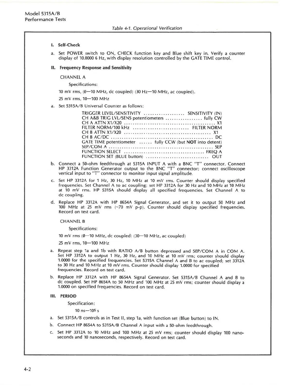
Table 4-1
Operational
Verification
I. Self-Check
a.
Set
POWER switch
to
ON,
CHECK
function
key and Blue shift key
in.
Verify
a
counter
display
of
10.0000 6 H
z,
with
displ
ay
reso
lution
co
ntrolled
by
the
GATE TIME
con
tr
ol.
II.
Frequency Response
and
Sensilivity
CHANNEL A
Specifications:
10
mV
rms, (
0-10
MHz,
dc
coupled
) (30 H
z-
10 M H
z,
ac coupled).
25
mV
rm
s,
10-100
M Hz
a.
Se
t
53
15A/ B Universal
Counter
as
fo
llows:
TRIGGER LEVEl/SENSIT
IV
I
TY
. . . . . .
..
.
..
. .
..
SENSITIVITY (IN)
CH
A&B TRIG
LV
L
/S
ENS
potentiometers..
.
fully
CW
CH A ATTN
Xl/X20
...
.
.....
. . .
.....
Xl
FI
LTER
NO
RM/
l00
kHz .
..
...
. . F
IL
HR
NORM
CH B A
TI
N
XlIX20
................
. . . .
..
...
Xl
CH B AC/ DC . . . . . . . . . . . . . . . . . . . . . . . . . . . .
..
DC
GATE
TI
ME
potentiometer
fu
lly
CCW
(
but
NOT
in
to
detent
)
SEP
/
COM
A
...
. . . . . .
..
. . .
...
. .
.. ..
...
.
....
SEP
FU
NCTI
ON
SELECT
...................
.
..
.
....
F
REQ
A
FUNCTI
ON
SET
(
BL
UE
button
)
......
...
. . .
...
..
OUT
b.
Connect
a 50-ohm
feedthrough
at
53
15A INPUT A
with
a BNC
"T"
connecto
r.
Connect
HP
33
1M
function
Generator
output
to
the BNC "T"
connector;
connect
oscilloscope
vertical i
nput
to
" T"
connector
to
mon
i
tor
input
signal
ampl
itude.
c.
Set
HP 3312A
for
1 H
z,
30
Hz. 10
MHz
at 10
mV
rms.
Counter
s
hould
display speci
fie
d
fre
quenci
es.
Set
Channel A
to
ac
coup
l
ing;
se
t
HP
3312A
fo
r
30
Hz and 10 M Hz at 10 M
Hz
at 10
mV
rms.
HP
53
15A should display all specified frequencies.
Se
t Channel A
to
dc
coupling.
d. Replace HP 3312A
with
HP 8654A Signal Generator, and set it
to
output
50
MH
z and
1
00
M Hz at
25
mV rms (-
70
mV
p-p
).
Counter
should display sp
ecified
frequencies.
Rec
ord
on
test card.
CHANNEL B
Specifications:
10
mV
rms (
0-10
MHz,
dc
coupled
)
(3
0-1
0 M H
z,
ac
couple
d)
25
mV
rms,
10-100
M
Hz
a.
Repeat step l a and
lb
wi
th
RATIO
Al
B
button
depressed and SEP/COM A in
COM
A.
Set
HP 3312A
to
ou
t
put
1 Hz,
30
Hz, and
10
M Hz at 10
mV
rms;
counter
should display
1.
0000
for
the
specified frequencies.
Set
5315A Channel A a
nd
B
to
ac
cou
pled
;
set
3312A
to
30
Hz and 10
MHz
at 10
mV
rms.
Counter
should
di
splay 1.0000
for
specified
frequencies.
Re
co
rd
on
test card.
b. Replace
HP
33
12A w
ith
HP
8654A Signal Genera
to
r.
Se
t
S31SA
/ B Channel A and B
to
dc
coupled.
Set
HP 8654A
to
50
MHz
and 100 M Hz at
2S
mV
rms;
counter
should
display a
1.0000
on
specified frequencies. Record
on
test card.
III. PERIOD
Speci
fic
ation:
10 ns-1OS s
a.
Set
5315A/ B cont
ro
ls
as
in Test II, step
la
, wi
th
function
set (Blue bu
tto
n)
to
IN.
b.
Connect
HP
8654A
to
53
15A/ B
Channe
l A
input
with
a
50
-o
hm
feed
through.
c.
Set
HP
331M
to
10
MHz
and
100
M Hz at
25
mV
rms; counter should display 100
nano-
seconds and 10 nanoseconds, respectivel
y.
Record
on
lest card.